Robot Arm Tutorials

Friday Facts 19: Marlin for Robot Arms

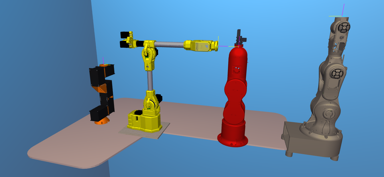
Today I’m going to show you how to set up Marlin firmware – the code in the robot brain – for your board so it thinks it is a robot arm and I will be using the Sixi 3 as my example. When we’re done we’ll have a 6 axis machine ready to receive gcode from apps like Robot Overlord.

Building a custom robot arm is easier if one uses common hardware. Thanks to the popularity of 3D printers it is now super easy to get stepper motors, limit switches, and MCUs that drive five, six, or even more motors. Marlin takes away all the headache and lets anyone talk to a robot with gcode, the standard language of CNC machines like 3D printers, mills, and lathes.

The major steps are:

  1. Fork Marlin
  2. Customize it
  3. Flash your board
  4. Test it

Fork Marlin

To “fork” is to make a special copy. it’s special because it includes a feature to update your copy with changes to the original. When the Marlin developers improve something, you can press a button and get all their updates.

The code for Marlin is available at https://github.com/MarlinFirmware/. I have a fork for robot arm Sixi 3 already started. You can get that fork as well right here: https://github.com/MarginallyClever/Marlin/

Make sure that (1) the branch is set to sixi3, then (2) click the code button and then (3) Open with Github Desktop or Download Zip. If it’s a ZIP you’ll have to unpack it somewhere like Documents/Github/Marlin.

Customize Marlin

Here’s a list of lines in Configuration.h that I’ve changed. The bold parts are unchanged so you can use that to search the file. The stepper motors in Marlin are named – internally only – as X, Y, Z, I, J, K.

#define STRING_CONFIG_H_AUTHOR “(Marginally Clever, Sixi3)”

#define MOTHERBOARD BOARD_RUMBA

#define CUSTOM_MACHINE_NAME “Sixi 3 robot arm”

#define EXTRUDERS 0

Because it’s a RUMBA board I also had to redefine a few of the pin settings. Normally all supported boards are defined in Marlin/src/pins/*.

#define I_STEP_PIN                         23
#define I_DIR_PIN                          22
#define I_ENABLE_PIN                       24
#define J_STEP_PIN                         26
#define J_DIR_PIN                          25
#define J_ENABLE_PIN                       27
#define K_STEP_PIN                         29
#define K_DIR_PIN                          28
#define K_ENABLE_PIN                       39

#undef Y_MAX_PIN
#undef Z_MIN_PIN
#undef Z_MAX_PIN

#define I_MIN_PIN                           34
#define J_MIN_PIN                           33
#define K_MIN_PIN                           32

The type of driver and the external name of each motor is next.

#define X_DRIVER_TYPE  A4988
#define Y_DRIVER_TYPE  A4988
#define Z_DRIVER_TYPE  A4988
//#define X2_DRIVER_TYPE A4988
//#define Y2_DRIVER_TYPE A4988
//#define Z2_DRIVER_TYPE A4988
//#define Z3_DRIVER_TYPE A4988
//#define Z4_DRIVER_TYPE A4988
#define I_DRIVER_TYPE  A4988
#define J_DRIVER_TYPE  A4988
#define K_DRIVER_TYPE  A4988

...

#ifdef I_DRIVER_TYPE
  #define AXIS4_NAME 'U' // :['A', 'B', 'C', 'U', 'V', 'W']
  #define AXIS4_ROTATES
#endif
#ifdef J_DRIVER_TYPE
  #define AXIS5_NAME 'V' // :['B', 'C', 'U', 'V', 'W']
  #define AXIS5_ROTATES
#endif
#ifdef K_DRIVER_TYPE
  #define AXIS6_NAME 'W' // :['C', 'U', 'V', 'W']
  #define AXIS6_ROTATES
#endif

Limit switches are tricky because the original Sixi 3 still doesn’t have them. (The plan is a new PCB that has always-on sensors). For Sixi 3 only, I have to trick the sensor code. When the robot turns on it will believe it has already homed, no matter where it is. A better robot with switches would call G28 to find home, and then the invert would depend on the type of switch (normally open vs normally closed) and I don’t remember what plug does.

#define USE_XMIN_PLUG
#define USE_YMIN_PLUG
#define USE_ZMIN_PLUG
#define USE_IMIN_PLUG
#define USE_JMIN_PLUG
#define USE_KMIN_PLUG

...

#define X_MIN_ENDSTOP_INVERTING false 
#define Y_MIN_ENDSTOP_INVERTING false 
#define Z_MIN_ENDSTOP_INVERTING false 
#define I_MIN_ENDSTOP_INVERTING false 
#define J_MIN_ENDSTOP_INVERTING false 
#define K_MIN_ENDSTOP_INVERTING false 
#define X_MAX_ENDSTOP_INVERTING true 
#define Y_MAX_ENDSTOP_INVERTING true 
#define Z_MAX_ENDSTOP_INVERTING true 
#define I_MAX_ENDSTOP_INVERTING false 
#define J_MAX_ENDSTOP_INVERTING false 
#define K_MAX_ENDSTOP_INVERTING false 

Motors also need gearbox and speed settings. Sixi 3 has a 70:1 harmonic gearbox and then a further pulley reduction in each unit. Since each motor does 200 steps per turn, that makes 105 steps per degree!

#define DEFAULT_AXIS_STEPS_PER_UNIT   { 105, 105, 105, 105, 105, 105 }

105 steps per degree * 5 deg/s = 525 steps per second. Impressive for such tiny NEMA17 motors. It might not be fast but it works and it’s affordable. Cheap, fast, good… pick two.

#define DEFAULT_MAX_FEEDRATE          { 5,5,5,5,5,5 }

#define CLASSIC_JERK // uncommented this to turn it on

#define S_CURVE_ACCELERATION // uncommented this to turn it on

I make sure to leave motors on so the arm doesn’t suddenly “go limp” at the worst time.

#define DISABLE_X false
#define DISABLE_Y false
#define DISABLE_Z false
#define DISABLE_I false
#define DISABLE_J false
#define DISABLE_K false

Range of motion is important, Marlin won’t let you go outside the limits. Remember this code was written for square box 3D printers, so some of the terms are a little silly for our needs.

// The size of the printable area
#define X_BED_SIZE 360
#define Y_BED_SIZE 360

// Travel limits (linear=mm, rotational=°) after homing, corresponding to endstop positions.
#define X_MIN_POS 0
#define X_MAX_POS 360
#define Y_MIN_POS 0
#define Y_MAX_POS 360
#define Z_MIN_POS 0
#define Z_MAX_POS 360
#define I_MIN_POS 0
#define I_MAX_POS 360
#define J_MIN_POS 0
#define J_MAX_POS 360
#define K_MIN_POS 0
#define K_MAX_POS 360

#define MIN_SOFTWARE_ENDSTOPS  // but no sub-values like MIN_SOFTWARE_ENDSTOP_X
#define MAX_SOFTWARE_ENDSTOPS  // but no sub-values like MAX_SOFTWARE_ENDSTOP_X

#define EEPROM_SETTINGS // save important data to EEPROM

#define SDSUPPORT

#define REPRAP_DISCOUNT_SMART_CONTROLLER // or your favorite flavor here

#define NUM_SERVOS 1 // for the gripper

Flash your board

Press the Compile button (1) to check for errors. Press the Upload button (2) to send it to your connected device. Press the Connect button (3) to open a serial monitor and check that your device says it is now a Marlin device. If all goes well, you’re ready to rock!

Test your new device

Even before your board is installed in an arm you should be able to home it with G28 and move it with G0/G1. Remember: every bug is just a test you didn’t run!

Final thoughts

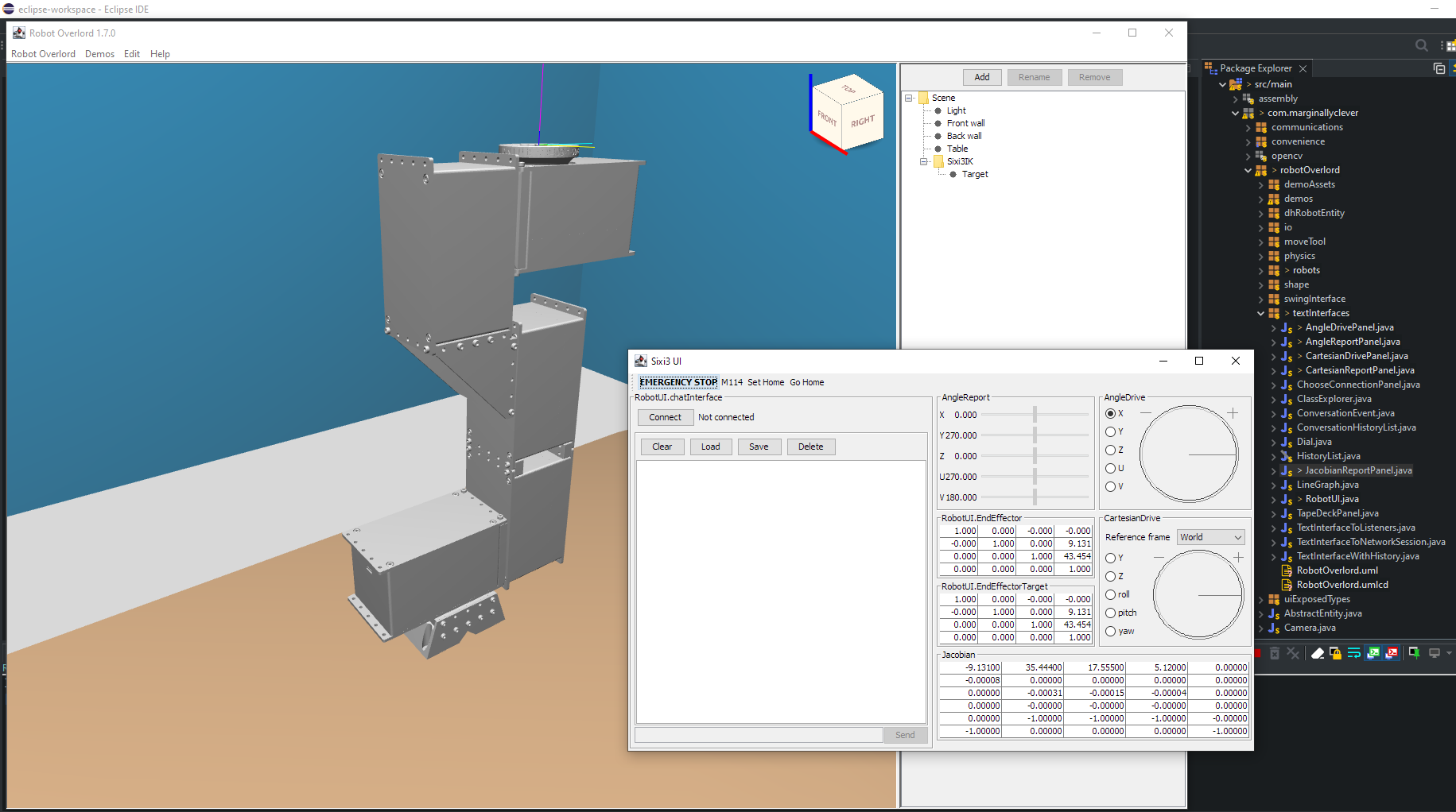
Now that you have a 3D printer board setup to run Marlin, it should be able to receive angle values as gcode. Each set is one forward kinematic pose of the arm. Moving between two poses will send the arm in curving arcs. Lots of poses close together will create the look of straight lines. Planning all those poses is easy for apps like Robot Overlord. That’s why I wrote it!

Got more questions? Something out of date in this post? Join us on Discord.

News

Friday Facts 14: All the Sixi robot arms so far (demo at end)

Discord user Wted00 said “You talk about Sixi 3 a lot. What ever happened to Sixi 1 and 2?” Great question, long answer. This video covers robot arms before Sixi and then all three models of the current brand, along with interesting things learned along the way. Plus stick around for movement demos at the end.

robot arms in Robot Overlord
News

Friday Facts 11: How to add a robot arm to Robot Overlord (2022)

Robot Overlord is going to be the inkscape, the VLC, the Steam of robot arms – the one vendor-agnostic interface everyone teaches, knows, and loves. In order to get there it has to support every robot arm under the sun. This post is for robot arm makers that want to save time by not writing all their own code.

Some of the arms already available

Did you know Robot Overlord speaks natively to Marlin 3D printer firmware? Save even more time by using the same firmware.

You will need

  • A 3D CAD model of your robot arm
  • The D-H parameters of the arm in the same pose as it appears in your CAD file
  • The ability to write Java code for the Robot Overlord project
  • Some familiarity with git (forks, commits, pull requests)

Prepare your CAD file

It is easiest to export your arm into discrete moving sections, all of which with the same origin at the bottom center of the base of the arm (see slide 1). This is the same origin as the D-H parameters.

A meca500 robot, color coded with the base and six parts. the origin would be in the red part, on the same axis of rotation as the pink part

To help Robot Overlord run smoothly and to protect your IP it is recommended that you decimate the model by removing all hidden internal structures and components. Consider leaving screw heads while removing the threaded sections to save many megabytes of file size.

Each discrete section should be exported as an OBJ or STL file. (more on this later.)

The exported files should be located in /src/main/resources/[your robot folder]/. So if your robot is named Foo then it would be /src/main/resources/foo/. It would be consistent to name them base, j0, j1, etc.

Prepare your Robot Overlord class

In Robot Overlord’s /src/main/java/com/marginallyclever/robotOverlord/robots/robotArm/implementations you will find the collection of currently supported robot arms. It may be easiest to copy one of these classes and modify it for your purposes. Here is the minimum needed to code your arm. Every instance of Foo should be replaced with your class name.

public class Foo extends RobotArmIK {
	private static final long serialVersionUID = 1L;

	public Foo() {
		super();
		setName("Foo v1");  // the name that appears to users.
	}
	
	@Override
	protected void loadModel() {
		setBaseShape(new Shape("Base","/Foo/j0.obj"));

		// The DH parameters and the model file, added in order from J0 ... J5.  
		// angles are degrees, distances are centimeters.
		// name d r alpha theta thetaMax thetaMin modelFile
		addBone(new RobotArmBone("X", 7.974,     0,270,  0,170,-170,"/Foo/j1.obj"));
		addBone(new RobotArmBone("Y", 9.131,17.889,  0,270,370, 170,"/Foo/j2.obj"));
		addBone(new RobotArmBone("Z",     0,12.435,  0,  0,150,-150,"/Foo/j3.obj"));
		addBone(new RobotArmBone("U",     0,     0,270,270,440, 100,"/Foo/j4-6.obj"));
		addBone(new RobotArmBone("V",15.616,     0, 90, 90,270,-90,"/Foo/j5-6.obj"));
		addBone(new RobotArmBone("W",  5.12,     0,  0, 180,360,   0,"/Foo/j6-6.obj"));

		adjustModelOriginsToDHLinks();
		setTextureFilename("/Foo/texture.png");
	}
}

Now that the arm can be loaded by the app it needs to be on the menu of things that can be created by the user. In /src/main/java/com/marginallyclever/robotOverlord/EntityFactory.java add your new class:

public class EntityFactory {
	private static Class<?> [] available = {
		// ...
		com.marginallyclever.robotOverlord.robots.robotArm.implementations.Mantis.class,
		com.marginallyclever.robotOverlord.robots.robotArm.implementations.Sixi2.class,
		com.marginallyclever.robotOverlord.robots.robotArm.implementations.Sixi3_5axis.class,
		com.marginallyclever.robotOverlord.robots.robotArm.implementations.Sixi3_6axis.class,
		com.marginallyclever.robotOverlord.robots.robotArm.implementations.Thor.class,
		com.marginallyclever.robotOverlord.robots.robotArm.implementations.Foo.class,  // "Foo" must be your class name.
	};
	// ...
}

Now when you run the application and open the Add menu your robot name will appear.

‘Foo v1’ will appear on this list

Model size and orientation fixes

It is possible that your model appears in Robot Overlord too large, too small, or the parts are rotated in a strange way. My solution is to use a modelling program like Blender to rotate, scale, decimate, and even texture the model.

Forward and Up will control the rotation. +Z is always up in a Robot Overlord scene.

Selection Only will simplify your exporting from Blender. In the image above it will only export J2.

Scale will control the size. For models that appear in meters instead of centimeters, choose 0.1. If your model is imperial, you’ll probably want 2.54.

Now share it with …the world!

You’ve changed the code, you’ve massaged the model, it runs on your machine. Now to share it with everyone else! A pull request from you to the Robot Overlord project will tell the dev team that your stuff is ready. This is the best way to make sure your model gets in the way you want it.

No time? Let us do it for you.

We can add your model(s) to our system. Contact us! We’re looking to collaborate and work with everyone. Writing the class is free; preparing the CAD files is specialized work we outsource and will quote.

What about URDF files?

URDF is the Unified Robot Description Format, part of ROS, the Robot Operating System. ROS is a nice system but much harder to get running – part of the reason I work on Robot Overlord. Join the Robot Overlord github project and help make it happen? Imagine what we could do together!

News

Friday Facts 3: Sixi 3 Java GUI

This week I’ve done a lot to make driving the Sixi 3 arm easier.

You’ll recall from FF1 that I had build a Panel to talk to a robot in Javax Swing.

TextInterfaceToListeners (at the bottom) was the starting point. Then I made a ConversationHistoryList (in the middle). The two are tied togeter in a TextInterfaceWithHistory, such that hitting send copies the message to the history and clicking a line in the history copies it to the input field. Next I made a ChooseConnectionPanel (at the top) and attached that to the TextInterfaceWithHistory inside a TextInterfaceToNetworkSession. Sure, it could have all been in one giant class… but that’s hard to manage, debug, or reuse.

Having made all that, I found it was no better than the existing Arduino serial interface for talking to the robot. My biggest worry is that I make a typo and send the robot crashing through the table before I can hit the emergency stop. So to address this pain point, I needed a way to drive more intuitively.

The Dial

The Dial is drawn to scale whatever size you need. It listens for scrolling of the mouse wheel. Other classes can subscribe to get ActionEvents when the dial moves. This way the dial is loosely coupled and can be reused all over the place. For example,

Angle Driving

Using the dial I built a panel that is initialized with a virtual sixi3 robot.

The radio buttons on the left are pulled from the robot model. The AngleDriving system listens to the dial. When the Dial moves then AngleDriving looks at the selected button, finds the robot joint, and tweaks it by 1 degree.

Cartesian Driving

Moving the arm one joint at a time is fine some of the time, but sometimes I need to move in a straight line. I improved the look of the Dial a little bit and made this tool to move the end effector (finger tip) of the robot arm.

XYZ are straight line moves. Roll is a twist around Z, pitch a twist around X, and yaw a twist around Y. Each of these moves happens relative to the reference frame. The options for now are world, the first joint of the robot, and the end effector itself.

Read-only panels

Once I had that I needed more ways to visualize what the system was doing. The two types I made are the AngleReportPanel,

And the various matrix reports.

Each of these listens to the robot reporting a change to the end effector position.

Cartesian Driving with Jacobians

Big shout out to https://akintokinematics.com/ for the excellent Jupyter notebooks that helped me improve cartesian driving to work. For some time now I’ve been telling everyone how much I love Gradient Descent for moving the robot arm. Well… it turns out Gradient Descent is hard to tune and slow AF to converge on a solution, sometimes taking 30 seconds per millimeter. So, instead, based on Greer’s notes, I used the approximate Jacobian.

The approximate Jacobian is a matrix describing the relationship between joint velocity and cartesian velocity at a position. So from position A to position B have the cartesian difference {x,y,z,roll,pitch,yaw}, dAB.

  • I get the approximate Jacobian at A, aj.
  • I get the inverse or pseudoinverse of the Jacobian, aji,
  • Multiply aji * dAB to get is the amount to move each joint in the arm.
  • Apply the joint change and measure the error term.

I set up a loop to run (at most) 20 times. In practical terms it never seems to run more than 2 or 3 per step, and feels blazing fast.

Putting it all together

If you run the development version of Robot Overlord today and use Demos > Sixi 3 you’ll get this view and be able to drive the virtual robot by playing with the controls. Tweaking the dials moves the virtual robot. Sixi 3 UI listens for those changes and sends them through the RobotUI.chatInterface so they show up in the history and they move the real machine (if connected).

My next Thing is figuring out a nice way to run programs: loops, sequences, patterns, wait for signal, send signal, conditionals, and so on. The virtual robot does not know anything about gcode and my gut says it would be a really big mess to spread gcode around the app. I would love to jazz with you about this and find a Good Way to achieve the Thing.