Robot Arm Tutorials

Friday Facts 19: Marlin for Robot Arms

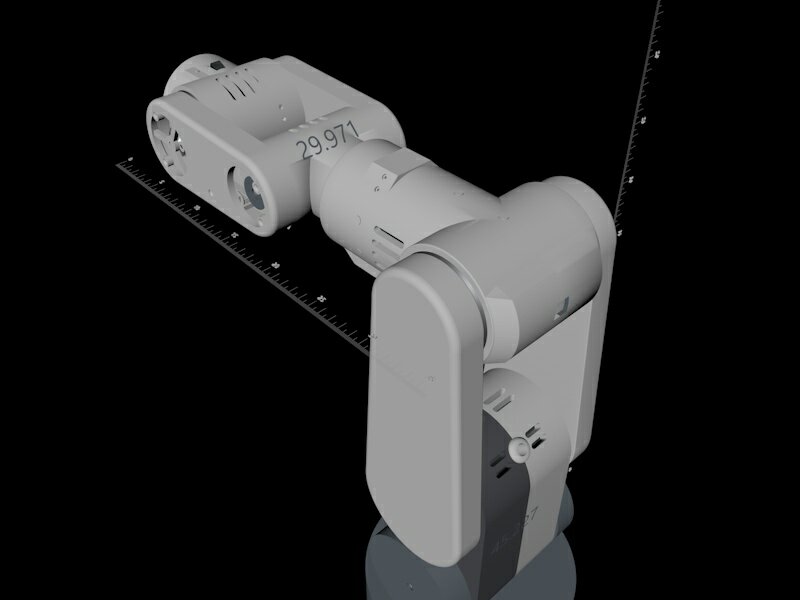
Today I’m going to show you how to set up Marlin firmware – the code in the robot brain – for your board so it thinks it is a robot arm and I will be using the Sixi 3 as my example. When we’re done we’ll have a 6 axis machine ready to receive gcode from apps like Robot Overlord.

Building a custom robot arm is easier if one uses common hardware. Thanks to the popularity of 3D printers it is now super easy to get stepper motors, limit switches, and MCUs that drive five, six, or even more motors. Marlin takes away all the headache and lets anyone talk to a robot with gcode, the standard language of CNC machines like 3D printers, mills, and lathes.

The major steps are:

  1. Fork Marlin
  2. Customize it
  3. Flash your board
  4. Test it

Fork Marlin

To “fork” is to make a special copy. it’s special because it includes a feature to update your copy with changes to the original. When the Marlin developers improve something, you can press a button and get all their updates.

The code for Marlin is available at https://github.com/MarlinFirmware/. I have a fork for robot arm Sixi 3 already started. You can get that fork as well right here: https://github.com/MarginallyClever/Marlin/

Make sure that (1) the branch is set to sixi3, then (2) click the code button and then (3) Open with Github Desktop or Download Zip. If it’s a ZIP you’ll have to unpack it somewhere like Documents/Github/Marlin.

Customize Marlin

Here’s a list of lines in Configuration.h that I’ve changed. The bold parts are unchanged so you can use that to search the file. The stepper motors in Marlin are named – internally only – as X, Y, Z, I, J, K.

#define STRING_CONFIG_H_AUTHOR “(Marginally Clever, Sixi3)”

#define MOTHERBOARD BOARD_RUMBA

#define CUSTOM_MACHINE_NAME “Sixi 3 robot arm”

#define EXTRUDERS 0

Because it’s a RUMBA board I also had to redefine a few of the pin settings. Normally all supported boards are defined in Marlin/src/pins/*.

#define I_STEP_PIN                         23
#define I_DIR_PIN                          22
#define I_ENABLE_PIN                       24
#define J_STEP_PIN                         26
#define J_DIR_PIN                          25
#define J_ENABLE_PIN                       27
#define K_STEP_PIN                         29
#define K_DIR_PIN                          28
#define K_ENABLE_PIN                       39

#undef Y_MAX_PIN
#undef Z_MIN_PIN
#undef Z_MAX_PIN

#define I_MIN_PIN                           34
#define J_MIN_PIN                           33
#define K_MIN_PIN                           32

The type of driver and the external name of each motor is next.

#define X_DRIVER_TYPE  A4988
#define Y_DRIVER_TYPE  A4988
#define Z_DRIVER_TYPE  A4988
//#define X2_DRIVER_TYPE A4988
//#define Y2_DRIVER_TYPE A4988
//#define Z2_DRIVER_TYPE A4988
//#define Z3_DRIVER_TYPE A4988
//#define Z4_DRIVER_TYPE A4988
#define I_DRIVER_TYPE  A4988
#define J_DRIVER_TYPE  A4988
#define K_DRIVER_TYPE  A4988

...

#ifdef I_DRIVER_TYPE
  #define AXIS4_NAME 'U' // :['A', 'B', 'C', 'U', 'V', 'W']
  #define AXIS4_ROTATES
#endif
#ifdef J_DRIVER_TYPE
  #define AXIS5_NAME 'V' // :['B', 'C', 'U', 'V', 'W']
  #define AXIS5_ROTATES
#endif
#ifdef K_DRIVER_TYPE
  #define AXIS6_NAME 'W' // :['C', 'U', 'V', 'W']
  #define AXIS6_ROTATES
#endif

Limit switches are tricky because the original Sixi 3 still doesn’t have them. (The plan is a new PCB that has always-on sensors). For Sixi 3 only, I have to trick the sensor code. When the robot turns on it will believe it has already homed, no matter where it is. A better robot with switches would call G28 to find home, and then the invert would depend on the type of switch (normally open vs normally closed) and I don’t remember what plug does.

#define USE_XMIN_PLUG
#define USE_YMIN_PLUG
#define USE_ZMIN_PLUG
#define USE_IMIN_PLUG
#define USE_JMIN_PLUG
#define USE_KMIN_PLUG

...

#define X_MIN_ENDSTOP_INVERTING false 
#define Y_MIN_ENDSTOP_INVERTING false 
#define Z_MIN_ENDSTOP_INVERTING false 
#define I_MIN_ENDSTOP_INVERTING false 
#define J_MIN_ENDSTOP_INVERTING false 
#define K_MIN_ENDSTOP_INVERTING false 
#define X_MAX_ENDSTOP_INVERTING true 
#define Y_MAX_ENDSTOP_INVERTING true 
#define Z_MAX_ENDSTOP_INVERTING true 
#define I_MAX_ENDSTOP_INVERTING false 
#define J_MAX_ENDSTOP_INVERTING false 
#define K_MAX_ENDSTOP_INVERTING false 

Motors also need gearbox and speed settings. Sixi 3 has a 70:1 harmonic gearbox and then a further pulley reduction in each unit. Since each motor does 200 steps per turn, that makes 105 steps per degree!

#define DEFAULT_AXIS_STEPS_PER_UNIT   { 105, 105, 105, 105, 105, 105 }

105 steps per degree * 5 deg/s = 525 steps per second. Impressive for such tiny NEMA17 motors. It might not be fast but it works and it’s affordable. Cheap, fast, good… pick two.

#define DEFAULT_MAX_FEEDRATE          { 5,5,5,5,5,5 }

#define CLASSIC_JERK // uncommented this to turn it on

#define S_CURVE_ACCELERATION // uncommented this to turn it on

I make sure to leave motors on so the arm doesn’t suddenly “go limp” at the worst time.

#define DISABLE_X false
#define DISABLE_Y false
#define DISABLE_Z false
#define DISABLE_I false
#define DISABLE_J false
#define DISABLE_K false

Range of motion is important, Marlin won’t let you go outside the limits. Remember this code was written for square box 3D printers, so some of the terms are a little silly for our needs.

// The size of the printable area
#define X_BED_SIZE 360
#define Y_BED_SIZE 360

// Travel limits (linear=mm, rotational=°) after homing, corresponding to endstop positions.
#define X_MIN_POS 0
#define X_MAX_POS 360
#define Y_MIN_POS 0
#define Y_MAX_POS 360
#define Z_MIN_POS 0
#define Z_MAX_POS 360
#define I_MIN_POS 0
#define I_MAX_POS 360
#define J_MIN_POS 0
#define J_MAX_POS 360
#define K_MIN_POS 0
#define K_MAX_POS 360

#define MIN_SOFTWARE_ENDSTOPS  // but no sub-values like MIN_SOFTWARE_ENDSTOP_X
#define MAX_SOFTWARE_ENDSTOPS  // but no sub-values like MAX_SOFTWARE_ENDSTOP_X

#define EEPROM_SETTINGS // save important data to EEPROM

#define SDSUPPORT

#define REPRAP_DISCOUNT_SMART_CONTROLLER // or your favorite flavor here

#define NUM_SERVOS 1 // for the gripper

Flash your board

Press the Compile button (1) to check for errors. Press the Upload button (2) to send it to your connected device. Press the Connect button (3) to open a serial monitor and check that your device says it is now a Marlin device. If all goes well, you’re ready to rock!

Test your new device

Even before your board is installed in an arm you should be able to home it with G28 and move it with G0/G1. Remember: every bug is just a test you didn’t run!

Final thoughts

Now that you have a 3D printer board setup to run Marlin, it should be able to receive angle values as gcode. Each set is one forward kinematic pose of the arm. Moving between two poses will send the arm in curving arcs. Lots of poses close together will create the look of straight lines. Planning all those poses is easy for apps like Robot Overlord. That’s why I wrote it!

Got more questions? Something out of date in this post? Join us on Discord.
News

Friday Facts 12: How to use Marlin in a Robot Arm

Building a robot arm is one thing, but what about writing the code to make it run? Some people want to learn the fine points of precision stepper motor control, forward and inverse kinematics, and then debug all that stuff. For the rest, working together gets the job done faster. For those people the Marlin 3D printer firmware is a great option. Today I’m going to show how I tweaked it to run in the Sixi 3 robot arm. Please share your experience with us so we can improve this post.

Marlin?

Marlin 3D printer firmware is the code in the brain of a very large number of printers. It is very flexible with a few changes. Most people might think of printers as having four motors – one for each direction and one for the extruder. But recent changes mean that Marlin can run up to six motors. That’s great for us, because most robot arms are 6 or less.

With Marlin installed you’ll be able to control the angle of each motor by sending gcode commands and even drive them simultaneously. With Marlin’s homing routines you could locate position, and new options coming in the near future will give real time feed back (more on that later)

What needs to be tweaked

Pour yourself a drink and settle in. This list will touch at least two files and take some time… OR you can use the sixi3 branch I maintain and adjust it for your speeds and gear ratios.

I keep trying new ways to make this list less dry. What do you think?

/Marlin/Configuration.h

Old valueNew Value
#define STRING_CONFIG_H_AUTHOR “(none, default config)”#define STRING_CONFIG_H_AUTHOR “(Sixi3, Marginally Clever Robots)”
#define MOTHERBOARD BOARD_RAMPS_14_EFB#define MOTHERBOARD BOARD_RUMBA
//#define CUSTOM_MACHINE_NAME “3D Printer”#define CUSTOM_MACHINE_NAME “Robot Arm”
//#define LINEAR_AXES 3#define LINEAR_AXES 6
#define AXIS4_NAME ‘A’#define AXIS4_NAME ‘U’
#define AXIS5_NAME ‘B’#define AXIS5_NAME ‘V’
#define AXIS6_NAME ‘C’#define AXIS6_NAME ‘W’
#define EXTRUDERS 1define EXTRUDERS 0
#define USE_XMIN_PLUG
#define USE_YMIN_PLUG
#define USE_ZMIN_PLUG
//#define USE_XMIN_PLUG
//#define USE_YMIN_PLUG
//#define USE_ZMIN_PLUG
//#define I_DRIVER_TYPE A4988
//#define J_DRIVER_TYPE A4988
//#define K_DRIVER_TYPE A4988
#define E0_DRIVER_TYPE A4988
#define I_DRIVER_TYPE A4988
#define J_DRIVER_TYPE A4988
#define K_DRIVER_TYPE A4988
//#define E0_DRIVER_TYPE A4988
#define DEFAULT_AXIS_STEPS_PER_UNIT { 80, 80, 400, 500 }#define DEFAULT_AXIS_STEPS_PER_UNIT { 105, 105, 105, 105, 105, 105 }
#define DEFAULT_MAX_FEEDRATE { 300, 300, 5, 25 }#define DEFAULT_MAX_FEEDRATE { 5, 5, 5, 5, 5, 5 }
#define DEFAULT_MAX_ACCELERATION { 3000, 3000, 100, 10000 }#define DEFAULT_MAX_ACCELERATION { 10, 10, 10, 10, 10, 10 }
//#define CLASSIC_JERK#define CLASSIC_JERK
//#define S_CURVE_ACCELERATION#define S_CURVE_ACCELERATION
#define E_ENABLE_ON 0 // For all extruders
//#define I_ENABLE_ON 0
//#define J_ENABLE_ON 0
//#define K_ENABLE_ON 0
//#define E_ENABLE_ON 0 // For all extruders
#define I_ENABLE_ON 0
#define J_ENABLE_ON 0
#define K_ENABLE_ON 0
#define INVERT_Y_DIR true#define INVERT_Y_DIR false
//#define INVERT_I_DIR false
//#define INVERT_J_DIR false
//#define INVERT_K_DIR false
#define INVERT_I_DIR false
#define INVERT_J_DIR false
#define INVERT_K_DIR false
//#define I_HOME_DIR -1
//#define J_HOME_DIR -1
//#define K_HOME_DIR -1
#define I_HOME_DIR -1
#define J_HOME_DIR -1
#define K_HOME_DIR -1
define X_BED_SIZE 200
define Y_BED_SIZE 200
//#define X_BED_SIZE 200
//#define Y_BED_SIZE 200
#define X_MIN_POS 0
#define Y_MIN_POS 0
#define Z_MIN_POS 0
#define X_MAX_POS X_BED_SIZE
#define Y_MAX_POS Y_BED_SIZE
#define X_MIN_POS -360
#define Y_MIN_POS 360
#define Z_MIN_POS -360
#define X_MAX_POS 360
#define Y_MAX_POS -360
//#define I_MIN_POS 0
//#define I_MAX_POS 50
//#define J_MIN_POS 0
//#define J_MAX_POS 50
//#define K_MIN_POS 0
//#define K_MAX_POS 50
#define I_MIN_POS -360
#define I_MAX_POS 360
#define J_MIN_POS -360
#define J_MAX_POS 360
#define K_MIN_POS -360
#define K_MAX_POS 360
#define HOMING_FEEDRATE_MM_M { (50*60), (50*60), (4*60) }#define HOMING_FEEDRATE_MM_M { (4*60), (4*60), (4*60), (4*60), (4*60), (4*60) }
//#define EEPROM_SETTINGS#define EEPROM_SETTINGS
//#define SDSUPPORT#define SDSUPPORT
//#define REPRAP_DISCOUNT_SMART_CONTROLLER#define REPRAP_DISCOUNT_SMART_CONTROLLER

/Marlin/Configuration_adv.h

define AXIS_RELATIVE_MODES { false, false, false, false }#define AXIS_RELATIVE_MODES { false, false, false, false, false, false }
#define HOMING_BUMP_MM      { 5, 5, 2 }
#define HOMING_BUMP_DIVISOR { 2, 2, 4 }
#define HOMING_BUMP_MM      { 5, 5, 5, 5, 5, 5 }
#define HOMING_BUMP_DIVISOR { 2, 2, 2, 2, 2, 2 }

Notes

  • MOTHERBOARD is your choice of brain board. Anything Mariln supports AND has 6 axies will work.
  • DEFAULT_AXIS_STEPS_PER_UNIT is the gear ratio at the given joint. For all sixi3 gearboxes the ratio is 70:1 (harmonic) * 54:20 (timing belt) * 200/360 (for 1.8 degree stepper motors at full step) = 105.
  • Because the gear ratio is so high the motors are not physically able to exceed the DEFAULT_MAX_FEEDRATE. If you use faster motors or a faster brain board you may be able to improve on these numbers.
  • EEPROM_SETTINGS, SDSUPPORT, and REPRAP_DISCOUNT_SMART_CONTROLLER are not required. I use these to tweak settings for testing, run programs from the SD card, and to have an LCD panel on my robot.
  • Every other change is to adjust from 3 axies to 6.

Homing and Real time feedback

There are some exciting new features coming to Marlin that should make real time feedback possible. This means we’ll know the robot position without having to guess or to home. It also means we can tell when the actual position deviates from the expected position too much that a collision has occurred and that can save a lot of trouble! The new configuration options to explore are:

  • REALTIME_REPORTING_COMMANDS adds some “quick commands” that get processed before anything else in the gcode buffer of the robot. Great for emergency breaking and for requesting position information (Gcode “S000”)
  • M114_REALTIME adds “M114 R” which reports the real-time position of the robot instead of the projected position at the end of the planned moves.
  • I2C_POSITION_ENCODERS is a first pass at adding real time sensors. This will no doubt be expanded later to include other types and features.

Further Reading

The Marlin Configuration guide online

News

Friday Facts 9: Daisy Stepper Driver 1.0

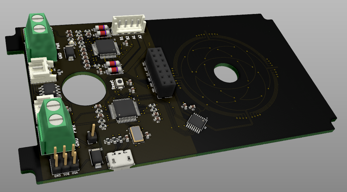
Daisy Stepper Driver is a closed-loop stepper controller that can be daisy-chained.

A stepper controller is a dual h-bridge circuit for controlling a stepper motor. You may be familiar with the A4988 stepper driver common in 2020s 3D printers. This board includes a more advanced model of the same. It can drive any one stepper motor at 24V up to 2A.

Closed-loop means that the board has a brain chip (MCU) that can read the motor position as well as direct. This way it can tell if it missed a step, bumped into something, is being driven, etc.

Daisy-chained means that they can be hooked sequentially. Sequential wires are much shorter. Shorter wires make for easier construction and repair. They are designed for up to 6 Daisies in a row. The Daisies talk to each other via the CANopen protocol.

The MCU is an STM32F103. In speaks CANopen natively while driving the stepper and listening to the sensor.

The CANopen master at the base of the robot can be any MCU that speaks CANopen. It synchronizes each motor and provides a single USB or bluetooth serial connection to the world.

What does this have to do with robots?

This board is designed to fit inside each gearbox of the Sixi 3 robot arm.

The old way a wire from every part had to run all the way through the arm and out the base. To replace the second joint from the bottom you would have to dismantle the entire arm. In the daisy chain model you only need to remove the elbow and disconnect the two cables to the next link in the chain.

Here’s a video of the arm moving IRL. Note the large cable hanging off the side – this version does not have the board in yet. It is the “outside” version of the wiring. I live in constant anxiety that they will get caught on something while moving.

Editor’s note – in this video one motor misbehaves. It was later found that the motor was negative 400-steps per turn instead of the expected 200-steps-per-turn.

Why isn’t the board in already?!

To test the board I have to be able to program it. To program the STM32F103 MCU I need to flash it with a bootloader via the programming pin J6. I have an STLINK V3 MINI to flash the bootloader BUT the MINI has male pins at 1.25mm pitch and my board’s J6 is 2.5mm pitch.

Editor’s note – I believe the larger connector is also a reversible connector.

Do you want to see this board get done? Say something nice on Discord.

What comes next?

Assuming this board is good and can be programmed… the next tasks are:

  • mount the board in the actuator
  • attach the disc to the output of the gearbox
  • run wires from one to the next and test the daisy chain
  • get an appropriate brain board and drive everything synchronously
  • make more boards

At the last stage it will be time to go to Kickstarter to scale production and bring the price down.

Did you design this board yourself?

No, and I’m proud of it! I have played with KiCAD in the past and done a few but this was beyond my skill. I found a great EE on Fiverr, gave him my specs, and he routed everything in a couple of days. Truly blown away by his skill. He even had a PDF step-by-step guide for ordering from PCBWay so I didn’t have to assemble the board or nothing.

Sadly, he closed his account and I have no way to reach him any more. Electroniikka! If you’re out there, know that I want to work with you again. I love working with talented people, it’s fun, easy, and it helps me scale up to the speed I long for.

Robot Arm

Can Machine Learning Improve Robot Kinematics?

I’ve tried several times to hand-code inverse kinematics for robot industrial arms in Robot Overlord.  To make a long story short, there are a lot of complicated edge cases that break my brain.  Many modern methods involve a lot of guess work in the path planning.  I know that a well trained Machine Learning agent could do the job much better, but to date there are none I can download and install in my robot.  So I’m going to try and do it myself.  Join me!

The problem I’m trying to solve with Machine Learning

I have a 3D model of my arm in the Java app called Robot Overlord.  The 3D model is fully posable.  At any given pose I can calculate the angle of every joint and the exact location and orientation of the finger tip.  I have Forward Kinematics (FK) which is a tool to translate joint angles into finger tip.  I have Inverse Kinematics (IK) which is a tool to translate the reverse.

A robot arm is programmed with a series of poses.  Go to pose A, close the gripper, Go to pose B, insert the part, Go to pose C, etc… The robot software has to calculate the movement of the arm between poses and then adjust every motor simultaneously to drive the finger tip along the path between the two poses.  I’ve already solved the firmware part to drive six motors given sets of joint angles.

The problem is that one IK solution there might be many combinations of joint angles – sometimes infinite solutions.  To illustrate this, hold a finger on the table and move your elbow.  Your finger tip didn’t move and you had lots of possible wrist/shoulder changes.  As the arm moves through space it can cross a singularity – one of the spots with infinite solutions – and when it comes out the other side the hand-written solution flips the some or all of the arm 180 degrees around.  A smarter system would have recognized the problem and (for instance) kept the elbow to the side.  I have tried to write better IK code but have not had any success.

My Machine Learning Plan of Attack

My plan is to use a Deep Learning Neural Network.  The DNN is a bit of a black box: on one side there is a layer of Inputs, on the other there is a layer of Outputs, and in between there are one or more hidden layers.  Inputs filter through the layers and come out as Outputs.  The magic is in the filtration process!  The filter can be trained with gradient descent using a cost function – if I can score every input/output combination I can let the DNN play with the virtual arm while the cost function watches and says “good, bad, better, worse” until the two work out all the best possible movements.

My Machine Learning Network design

I believe my inputs should be:

  • Arm starting pose: 6 random angle values.  Because DNN inputs are values in the range 0…1 I’ll say 0 is 0 degrees and 1 is 360 degrees.
  • Arm ending pose: 3 random position values and 3 random angle values.  Position values are scaled over the total movement range of the robot.  So if the robot can move on the X axis from -50 to +50, (x/100+0.5) would give a value 0…1.
  • Interpolation between both poses: 1 decimal number.  0 means at the start pose and 1 means at the end pose.

I want my outputs to be:

  • Arm joint angles: 6 angle values.
  • confidence flag: 1 number.  0 means “I definitely can’t reach that pose” and 1 means “I can reach that pose”.

The cost function should work in two steps:

  1. make sure there is no error in the joint value – that is to say, the finger is actually on the path where it should be, and
  2. seek to reduce joint acceleration.  Adjust the elbow and the wrist ahead of time to avoid the need to suddenly twist.

I’m going to try first with two hidden layers, then experiment from there.  I intuitively guess it will take at least two layers because there are two parts to the cost function.

My Machine Learning code setup

Robot Overlord source code is already written in Java so I’ve added TensorFlow and DL4J.  Currently I’m still walking through the MNIST quickstart tutorials and asking the DL4J chat room for help.  They already solved a few head scratching differences between the DL4J quickstart tutorials and the DL4J up-to-date examples.  You can find my first test in Robot Overlord’s code at /src/main/java/com/marginallyclever/robotOverlord/DL4JTest.java

Next

I hope that I’ve described my challenge thoroughly.  Please feel free to look at the code and make pull requests, or comment below or in the forums with any tips and advice you might have.  If you’re feeling helpful but not sure how, please share this far and wide so that I can reach the people who have the DNN know-how.

Stay awesome!