News

Friday Facts 4: How to Marlin Polargraph

Assuming you have two stepper motors, two limit switches, some timing belt, a 3D printer control board, and a hobby servo then you have everything you need to make a wall hanging plotter of your own that will work with Makelangelo Software. Read on for firmware configuration.

All the changes described herein have been applied to the fork of Marlin we maintain on Github. Make sure you are working with the branch called 2.1.x-polargraph which should match this blog post. You can modify this setup for your custom board. Many people have successfully built RAMPS+mega derivatives and shared their success stories in the Discord channel.

You’ll need to open the firmware in an Integrated Development Environment like Visual Studio Code and install the PlatformIO plugin.

The main files we’ll touch are Marlin\Configuration.h and Marlin\Configuration_adv.h. First I will show the line to find and then explain what is changed and why.

Marlin\Configuration.h

#define MOTHERBOARD BOARD_RAMPS_14_EFB

This sets the type of brain board you are using. The full list can be found in Marlin\src\pins\pins.h. In my case I change BOARD_RAMPS_14_EFB to BOARD_RUMBA.

#define CUSTOM_MACHINE_NAME "3D Printer"

Change 3D Printer to Polargraph. It’s aesthetic and non-essential.

#define EXTRUDERS 1

Polargraphs have no extruders. Change 1 to 0.

//#define POLARGRAPH

I remove the // part in front of # so that it becomes defined.

#define HYPOTENEUSE_LENGTH_AT_HOME_POSITION 1035.0

Makleangelo uses 1m belts. The pen holder adds a small amount to that and so my length for both belts is 1035. Correct belt length is essential to getting square drawings. While this is the default number in Marlin, you may have to change it – especially if you are making a huge machine.

Image
Image

100mm (radius of pen holder) – 14.466 (curved part of belt over pulley) – 50 (straight part of belt from switch to pulley) = 35.53400. That’s how a 1m belt becomes a hypoteneuse of 1035.

For Makelangelo huge 2035 worked great on 2m belt. From this I conclude that (the length of the pen holder arms) – (the part of the belt lost inside the motor mount) = +35mm. If you make a custom pen holder or different motor mounts your 35 will change.

#if MOTHERBOARD == BOARD_RUMBA
  #define X_MAX_PIN       35
  #define Y_MAX_PIN       34
#endif

These are the digital pins that are connected to your limit switches, uses for homing. When homing the machine will move the pen down and the counterweights up until the weights touch the switches. That is the maximum reach of each belt, and thus the max limit switch. For most boards, including RAMPS, you can ignore these lines so long as your switches are wired to x max and y max, respectively. These are here because RUMBA usage for polargraph predates Marlin adoption and Marlin needed to be made backward compatible for all existing customers.

#define USE_XMIN_PLUG
#define USE_YMIN_PLUG
#define USE_ZMIN_PLUG

I disable using minimum limit switch by adding // at the start of these lines.

//#define USE_XMAX_PLUG
//#define USE_YMAX_PLUG
//#define USE_ZMAX_PLUG

I enable using maximum limit switch by removing the // at the start of these lines.

#define X_MAX_ENDSTOP_INVERTING true // Set to true to invert the logic of the endstop.
#define Y_MAX_ENDSTOP_INVERTING true // Set to true to invert the logic of the endstop.
#define Z_MAX_ENDSTOP_INVERTING true // Set to true to invert the logic of the endstop.

I have switches wired to go LOW when they are clicked. If you have it the opposite then you’ll want to leave these set to false.

#define E0_DRIVER_TYPE A4988

There is no E0 Driver and the sanity checks in Marlin will get mad if this is defined. Put another // at the start of the line.

#define X_DRIVER_TYPE  A4988
#define Y_DRIVER_TYPE  A4988

If you are using something other than an A4988 stepper driver for your motor… this is where you’d list it.

#define DEFAULT_AXIS_STEPS_PER_UNIT   { 80, 80, 400, 500 }

There are only three axies of motion on this system, so we have to change it from { 80, 80, 400, 500 } to { 80, 80, 80 }. That assumes 200 step-per-turn motors and a 20 tooth GT2 pulley at 1/16 microstepping. (200*16) / (20*2)=80. Adjust your numbers accordingly. a 400-step motor would be 160 for the first two. The third is not really important because we don’t use a third stepper motor. Marlin won’t let me set two axies so it dangles on the end there like a vestigial tail.

#define DEFAULT_MAX_FEEDRATE          { 300, 300, 5, 25 }

I have changed these to { 90*60, 90*60, 90*60 }. Experiment with this number and see what kind of speeds you can get!

#define DEFAULT_MAX_ACCELERATION      { 3000, 3000, 100, 10000 }

I set mine to { 40*60, 40*60, 40*60 }. Another area I encourage you to experiment.

//#define CLASSIC_JERK

I don’t remember why I had to remove the // part but I did to appease the sanity checks.

#define INVERT_X_DIR false

By default Makelangelos are built with the left motor physically wired backwards so that “pull in” and “push out” was the same for both. So I have to change false to true. Discord user CaptFuture pointed out if you are building a DIY machine be aware mixing the wiring and the inversion might make some motors behave backwards.

//#define NO_MOTION_BEFORE_HOMING // Inhibit movement until all axes have been homed.
//#define HOME_AFTER_DEACTIVATE   // Require rehoming after steppers are deactivated.

I removed // from both. Safety third, right after chainsaws and LSD.

#define X_HOME_DIR -1
#define Y_HOME_DIR -1
#define Z_HOME_DIR -1

I changed these to 1 so that it homes to the maximum limits.

#define X_BED_SIZE 200
#define Y_BED_SIZE 200

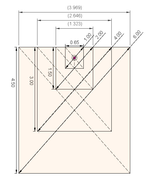
Here I set the X_BED_SIZE to the width of a Makelangelo. The width is measured from one motor shaft center to the other motor shaft center. Makelangelo 5 is 650mm. For the Makelangelo height I used 1000mm (1m). More on this in a minute. Note: this number cannot be an odd number.

#define X_MIN_POS (-X_BED_SIZE/2)
#define Y_MIN_POS (-Y_BED_SIZE/2)

The bottom-left corner of the drawing area would then be – X_BED_SIZE/2 and -Y_BED_SIZE/2, or -325 and -500, respectively.

#define X_MAX_POS (X_BED_SIZE/2)
#define Y_MAX_POS (Y_BED_SIZE/2)

The top-right corner of the drawing area would then be X_BED_SIZE/2 and Y_BED_SIZE/2, or 325 and 500, respectively.

//#define BED_CENTER_AT_0_0

I removed the //. You can tell from the math that it should be true.

//#define MANUAL_X_HOME_POS 0
//#define MANUAL_Y_HOME_POS 0

First I remove the //. Then the MANUAL_Y_HOME_POS is equal to -482.65. I get that number from

Y_MAX_POS - ( sqrt( sq(POLARGRAPH_MAX_BELT_LEN) - sq(X_BED_SIZE/2) ) )

Remember using the triangle adjacent and the opposite to get the hypoteneuse? well here we use the opposite (machine bed size) and the hypoteneuse (the belt length) to get the adjacent, and then adjust by the Y_MAX_POS.

Image courtesy of Discord user PO

Note that the final value has to be inside the allowable drawing area of the machine – you can’t home to a spot that’s outside the printable area. That means the -Y_BED_SIZE/2 has to be a larger negative number than the MANUAL_Y_HOME_POS. With my settings -Y_BED_SIZE/2 is -500 and everything is fine.

//#define EEPROM_SETTINGS

remove the //. EEPROM_SETTINGS will allow you to tweak some firmware settings like acceleration and steps/mm from the LCD panel and then save them to the printer’s (very tiny) memory. Worth it!

//#define SDSUPPORT

If you have an SD card slot, remove the //.

//#define NUM_SERVOS 3

I set this to 1. As Jack Black said, one’s all you need.

//#define DEACTIVATE_SERVOS_AFTER_MOVE

Remove the //. This keeps the servo from jittering when not being used, which makes for a more pleasant sounding machine. It is reactivated every time it is used, don’t worry.

Marlin\Configuration_adv.h

#define AXIS_RELATIVE_MODES { false, false, false, false }

Change to { false, false, false } because there are three axies and zero extruders. Keeps the sanity check happy.

#define MICROSTEP_MODES { 16, 16, 16, 16, 16, 16 } // [1,2,4,8,16]

Change to { 16, 16, 16 } to keep the sanity check happy. Same reason. This is where you’d set your microstepping values.

#define MANUAL_FEEDRATE { 50*60, 50*60, 4*60, 2*60 }

I changed to { 50*60, 50*60, 4*60 }. Three axis! THREE.

#define G0_FEEDRATE 3000 // (mm/min)

I changed the number to 12000. What can I say? I like to go fast.

LCD panels

Discord member Headly pointed out that there’s no mention of LCD control panels. Search Configuration.h for “LCD / Controller Selection” and then start reading. There are many choices from which to choose. For Makelangelo I use

#define REPRAP_DISCOUNT_SMART_CONTROLLER

If your Makelangelo has no LCD panel you must DISABLE this feature. When the robot is told to change pens (Gcode M0) it will wait for the user to click the dial. With no dial and no LCD, the user will be confused while the robot patiently waits forever.

While the previous Makelangelo-firmware talked at 57600 Baud, Marlin defaults to 250000. If you connect the app to your firmware and nothing is “heard” from the robot then the app and the robot are on two different baud rates.

Discord member Mesut asked about the minimum temperature settings in Marlin. There is no extruder so minimum temp settings are ignored by Marlin.

Help! Every G0 move goes to center!

Most motherboards that run Marlin have a small amount of EEPROM memory that needs to be initialized once to hold tweakable settings like top speed and machine dimensions. By default they are all zero, which makes math fail in the firmware and sends the pen holder to 0,0 on every move.

If you have an LCD panel connected to your machine the firmware should request a firmware reset at startup.

Another way is to connect over serial and send two commands: Reinitialize your EEPROM with an M502 factory reset, then save your EEPROM changes with an M500. Recheck that your machine width and height is not zero with an M503.

Custom hardware and DEFAULT_AXIS_STEPS_PER_UNIT

If you are building a custom machine, be aware that there are more settings to check. The DEFAULT_AXIS_STEPS_PER_UNIT is calculated this way:

( motor total steps per turn * microstepping ) / ( pulley pitch circumference )

Makelangelo uses 200 steps-per-turn motors and 16 microsteps. The pulleys are 20 tooth GT2 pulleys, or 40mm pitch circumference. That means our math is 200 * 16 / 20 or 80 steps per unit.

Be sure to check that your microstepping switches/jumpers match your math!

Final thoughts

After all these changes you should be able to upload the firmware and start running your polargraph drawing robot. Take it in small steps – try homing your machine with no belts on and then touch the switches to see if it behaves. Also check the pulleys turn the correct direction before putting the belts on.

By default Makelangelo software uses a servo position of 90 (middle of the range) for pen up and 40 for pen down. Keep that in mind when you install the servo horn (the finger thing that lifts).

If you have any trouble with this, please join me and other polagraph fans on the Discord channel. It may be you’re doing something exotic; maybe this document needs a refresh; or you just want to find people with similar tastes. Join us!

Further Reading

The Marlin Configuration guide online

You can find more serial commands at https://marlinfw.org/meta/gcode/

News

Friday Facts 3: Sixi 3 Java GUI

This week I’ve done a lot to make driving the Sixi 3 arm easier.

You’ll recall from FF1 that I had build a Panel to talk to a robot in Javax Swing.

TextInterfaceToListeners (at the bottom) was the starting point. Then I made a ConversationHistoryList (in the middle). The two are tied togeter in a TextInterfaceWithHistory, such that hitting send copies the message to the history and clicking a line in the history copies it to the input field. Next I made a ChooseConnectionPanel (at the top) and attached that to the TextInterfaceWithHistory inside a TextInterfaceToNetworkSession. Sure, it could have all been in one giant class… but that’s hard to manage, debug, or reuse.

Having made all that, I found it was no better than the existing Arduino serial interface for talking to the robot. My biggest worry is that I make a typo and send the robot crashing through the table before I can hit the emergency stop. So to address this pain point, I needed a way to drive more intuitively.

The Dial

The Dial is drawn to scale whatever size you need. It listens for scrolling of the mouse wheel. Other classes can subscribe to get ActionEvents when the dial moves. This way the dial is loosely coupled and can be reused all over the place. For example,

Angle Driving

Using the dial I built a panel that is initialized with a virtual sixi3 robot.

The radio buttons on the left are pulled from the robot model. The AngleDriving system listens to the dial. When the Dial moves then AngleDriving looks at the selected button, finds the robot joint, and tweaks it by 1 degree.

Cartesian Driving

Moving the arm one joint at a time is fine some of the time, but sometimes I need to move in a straight line. I improved the look of the Dial a little bit and made this tool to move the end effector (finger tip) of the robot arm.

XYZ are straight line moves. Roll is a twist around Z, pitch a twist around X, and yaw a twist around Y. Each of these moves happens relative to the reference frame. The options for now are world, the first joint of the robot, and the end effector itself.

Read-only panels

Once I had that I needed more ways to visualize what the system was doing. The two types I made are the AngleReportPanel,

And the various matrix reports.

Each of these listens to the robot reporting a change to the end effector position.

Cartesian Driving with Jacobians

Big shout out to https://akintokinematics.com/ for the excellent Jupyter notebooks that helped me improve cartesian driving to work. For some time now I’ve been telling everyone how much I love Gradient Descent for moving the robot arm. Well… it turns out Gradient Descent is hard to tune and slow AF to converge on a solution, sometimes taking 30 seconds per millimeter. So, instead, based on Greer’s notes, I used the approximate Jacobian.

The approximate Jacobian is a matrix describing the relationship between joint velocity and cartesian velocity at a position. So from position A to position B have the cartesian difference {x,y,z,roll,pitch,yaw}, dAB.

  • I get the approximate Jacobian at A, aj.
  • I get the inverse or pseudoinverse of the Jacobian, aji,
  • Multiply aji * dAB to get is the amount to move each joint in the arm.
  • Apply the joint change and measure the error term.

I set up a loop to run (at most) 20 times. In practical terms it never seems to run more than 2 or 3 per step, and feels blazing fast.

Putting it all together

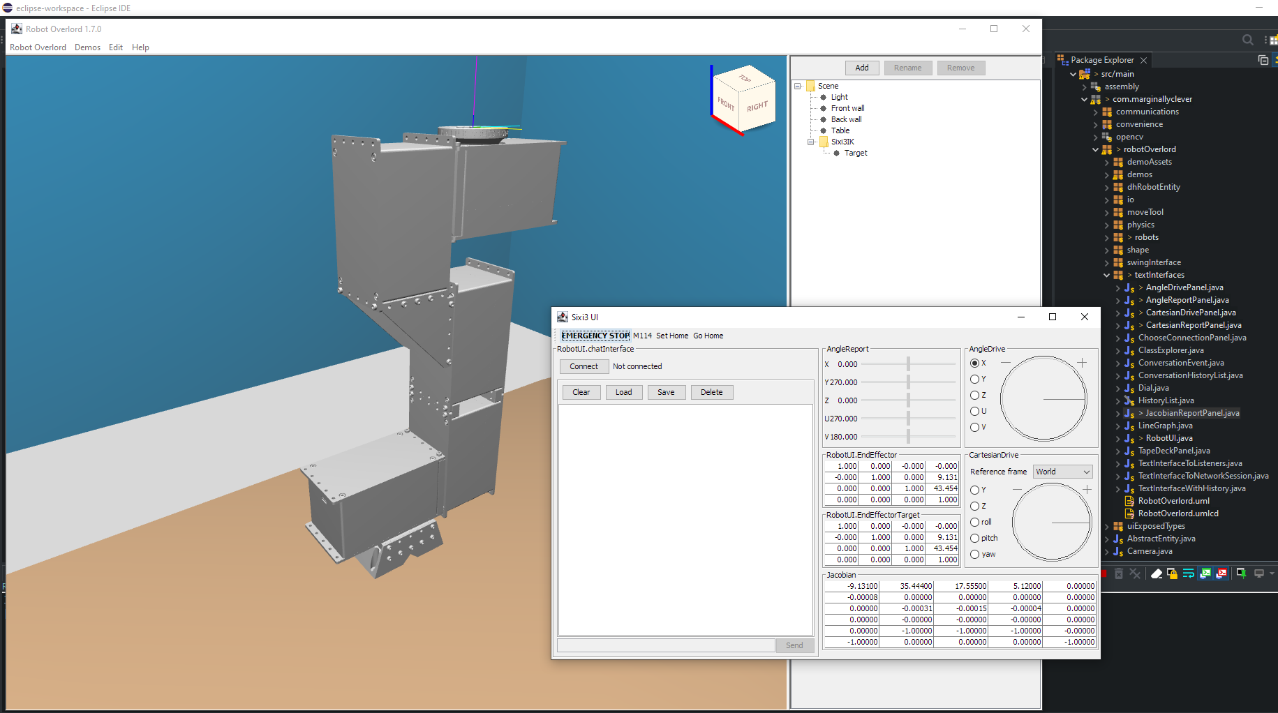
If you run the development version of Robot Overlord today and use Demos > Sixi 3 you’ll get this view and be able to drive the virtual robot by playing with the controls. Tweaking the dials moves the virtual robot. Sixi 3 UI listens for those changes and sends them through the RobotUI.chatInterface so they show up in the history and they move the real machine (if connected).

My next Thing is figuring out a nice way to run programs: loops, sequences, patterns, wait for signal, send signal, conditionals, and so on. The virtual robot does not know anything about gcode and my gut says it would be a really big mess to spread gcode around the app. I would love to jazz with you about this and find a Good Way to achieve the Thing.

News

Friday Facts 2: Makelangelo Java GUI

This last week there has been work on Makelangelo software to make it work with the new firmware.

I spent a lot of time using design patterns to decouple classes so they can be independently tested. Usually this means an Observer pattern common in Java: a visible Panel on the screen has a list of registered Listeners and when something interesting happens in the Panel it calls notifyListeners(interestingEvent). This way Panel can be run and tested without needing any specific Listener.

A single sub-panel

I’d like to change up the code for a MakelangeloRobot to be decoupled from the NetworkSession – the source of data from the real machine. Then data could come from, say, a piece of code reading from a file. That way the state of the machine could be recorded and played back for testing things like “is the machine connecting to you a Makelangelo 5, a 3, a 2, or something else?”

I’m also plagued by ideas about how a Turtle path is used by a MakelangeloRobot. Turtle is a class that contains TurtleMoves, which describe the movement of the pen over the paper. One Turtle per color! Based on the old Commdore 64 turtle, one of the first procedural drawing programs I used as a kid.

Many classes in the Makelangelo app read and manipulate the history of TurtleMoves in a Turtle.

Drawing speed vs quality testing

In a cartesian plotter the velocity, acceleration, and jerk have the same effect everywhere across the work area. Testing such a machine to find ideal speeds is not onerous. I would draw a grid of squares and on the x axis each square would have more velocity while on the y axis each square would have greater acceleration. In this way the sweet spot is easy enough to find.

In a polargraph plotter the challenge is much greater. What works at the top doesn’t work at the bottom, what works in the center might not work on the sides. Simply drawing a set of squares isn’t enough! Long story short I need your help to find the sweetest of sweet spots. Together we can do it. Right? Right??

Spiral improvements

before
after

…and that’s all I have to say about that.

Final thoughts

These changes can be downloaded from the Makelangelo project on Github.

Did you know you can add bars to your timing belt? I didn’t.

Join our Discord to talk more about this post.

Makelangelo News Robot Arm

Friday Facts 1: Sixi 3 update

This week I worked on the Sixi 3 arm quite a lot.

Coding

Monday, I made a new tool to talk to my robots. Arduino Serial monitor is all well and good but I needed more features and some color coding.

Sixi 3

Tuesday I tackled a problem with the base of the robot. When I designed the first version it seemed fine! Then I tried to drive it while in a Zoom meeting for the Vancouver Robotics Club and discovered that at the right spot the base and the J1 actuator collide.

Whoops. So I designed and 3D printed a new base…

…which didn’t work! The screws to attach the base to the board could not be accessed after the base was on the J0 gearbox. No tool clearance is bad! Taking the whole robot off the board just to fix J0 is bad! So that went in the recycling and I tried again.

That worked much better!

The screws that go on an angle through the top and bottom halves of the base need a nut. The nut can’t turn. I could make a really tight slot that the nut barely fits into… but then how do i get the nut out later? My solution is these nut holding tools. They fit snugly, prevent the nut from turning, and give me a convenient handle to grab with pliers when I need to pull them out. A gift to my future self!

Makelangelo 5

As you know from the previous post, there’s a new firmware coming that is faster, smoother, and much more friendly to all they DIY people out there. Much of this week has been talking with people on Discord, showing them how to set up their custom versions. In short,

  • Install the apps mentioned in https://mcr.dozuki.com/Guide/How+to+upload+Makelangelo-firmware+from+Windows+(2021+)/33?lang=en
  • Get the firmware currently at https://github.com/i-make-robots/Marlin-polargraph
  • read Marlin/Configuration.h and change where needed for your board, your drivers, your LCD.
  • For size changes and more advanced stuff, come talk with us!

I’ve also filmed raw footage about how to use 3M hooks to put a Makelangelo on a flat wall. Some people don’t like the suction cups or they don’t have a big window. No problem! Subscribe to my Youtube channel and watch for the announcement.

News

ROS 2021: intimidating and unfriendly

ROS on Windows is a needlessly difficult process. Read on for tips and thoughts.

For added fun, make it a drinking game! Every time something seems stupid, if it makes you lol, if you breath extra hard through your nose, or shake your head, take a sip. Maybe bring the whole bottle because you will be refilling and quite drunk by the end.

Installing ROS

The first place to go is https://www.ros.org/install/ . I chose “Get ROS Foxy Fitzroy on Ubuntu Linux, macOS, or Windows 10”, which leads to https://docs.ros.org/en/foxy/Installation.html . Already I’m having my doubts – where any other program would just download a windows installed and do the job, this thing wants you to start reading install documentation. I chose Binary Packages > Windows, because maybe it’s just one more click away. Nope!

The installer that should do all of that doesn’t exist? FINE, I’ll do it myself.

So how bad is installing Chocolatey?

Take a moment to find the install button. Notice how they seem to care more about why you should install than getting you installed. This is because they need you to really want it so that you will fight through the next steps, a masterpiece of understated comedy.

I came here to install, not subscribe to your newsletter.

The average person has already said “nope” and quit. But I’m in it for the lulz, I guess, so let’s see. I guess I’m an individual, so let’s pop open that administrative shell… Lenovo has a howto … and disable security on my Windows to get this thing in, always a good idea…

5. If you don’t see any errors, you are ready to use Chocolatey! Type choco or choco -? now, or see Getting Started for usage instructions.

What does “no errors” look like?

So friendly! Now keep that powershell open because the next steps (remember, the next steps? We were installing ROS) will want it.

Install Python and Visual C++ Redistributables

Actually, this was copy + paste + wait and not terrible. Not great, but not painful. Leave that powershell open for later.

Installing OpenSSL

The instructions are clear, here. The page I’m sent to looks like Geocities 1995. It looks like the emails Rachel in marketing sends, reply all, marked important. Super trustworthy.

Why would anyone need a screenshot of the installer? Who does that?

I’ve highlighted the link you’re looking for. Finally! A real installer! Wow! I bet when that was built they felt ahead of their time. Anyways, now it’s back to the ROS install steps. Which one are we on now, 203? 206?

But wait, there’s more!

Oh, apparently OpenSSL doesn’t install everything it should because reasons. They say I have to add something to the PATH variable, which is the Windows version of a vestigial organ, like a hindbrain or an appendix.

Leave this window open because we’ll be back!

Install Visual Studio 2019

Well…. no. I already have Visual Studio Code, which has a ROS extension.

Why do they call it visual studio? There’s no Auditory Studio. there’s no Tactile Studio. It doesn’t let me edit pictures, I can’t even embed meme gifs as method names. What marketing team came up with this? Was it the least garbage name still available?

Install additional DDS implementations (optional)

Since I have no idea what this means, I’m skipping it. A single sentence explanation would have been nice.

Install OpenCV and dependencies

Apparently OpenCV isn’t strictly necessary, and I’ll err on the side of caution and put it in anyways.

Next they want me to install cmake. So I’m using one installer to install another installer because nobody wants to play nice with a Windows installer. It’s starting to feel like robotics is hard because somebody wants it to be hard.

What’s next?

Please download these packages from this GitHub repository.

– asio.1.12.1.nupkg

– bullet.2.89.0.nupkg

– cunit.2.1.3.nupkg

– eigen-3.3.4.nupkg

– tinyxml-usestl.2.6.2.nupkg

– tinyxml2.6.0.0.nupkg

– log4cxx.0.10.0.nupkg

The page at the link has eight packages and you only need seven. Also the “download source” will not help you get all of them in a single click, because that would be against the ethos. That being the ethos set by people fired from the department of motor vehicles for being too frustrating.

Python problems

The instructions say to use powershell and paste this:

python -m pip install -U catkin_pkg cryptography empy ifcfg lark-parser lxml netifaces numpy opencv-python pyparsing pyyaml setuptools rosdistro

python cannot be found because it is not in the PATH variable. Rather than touch PATH again, I changed the start of the line to say c:\phython38\python -m… which worked better. And by better I mean a screaming red page of angry text.

Oh, so all of that was caused because something called pip was out of date? Why wasn’t it upgraded to the latest when I installed? I have to do it manually? Fine. c:\python38\python -m pip install –upgrade pip. After that I was able to run the previous command again and get a full install. Note that there were warnings in white text mixed into the other no-problem white text. If you don’t see the warnings do you have to worry about them?

Back to dependencies

“You agreed to having a pineapple put up your butt, but now I need you to confirm you also want lube.”

I hope you still have that PATH editor open, coz you still need it here! The instructions say I need to add C:\Program Files (x86)\GraphvizX.XX\bin and the powershell chocolatey said it installed to C:\Program Files\Graphviz\bin. I did the second one.

Downloading ROS 2

Remember ROS? We were installing ROS. Apparently we’ve made it through the desert and reached mount Sinai.

It is normal that the previous command, if nothing else went wrong, outputs “The system cannot find the path specified.” exactly once.

Well, about that.

So… the thing that was optional wasn’t actually? Hm. Well, the next step says to run demos and they don’t work. The step after that says Troubleshooting so I’ll just click o-oooooh wait a second, what is this?

This whole time it could have been

  • install chocolately
  • make chocolately install ROS.
  • C:\dev\ros2_foxy\local_setup.bat

?

Nope.

Although the earlier steps failed and the alternative ROS 2 build instructions worked, the demos fail to run. They say run these commands in two separate powershells:

  • ros2 run demo_nodes_cpp talker
  • ros2 run demo_nodes_py listener

Do they work? No. “ros2” does not exist on the system. “ros2.*” cannot be found anywhere in the c:\opt folder.