News

Friday Facts 14: All the Sixi robot arms so far (demo at end)

Discord user Wted00 said “You talk about Sixi 3 a lot. What ever happened to Sixi 1 and 2?” Great question, long answer. This video covers robot arms before Sixi and then all three models of the current brand, along with interesting things learned along the way. Plus stick around for movement demos at the end.

News

Friday Facts 13: How to find DH parameters for your robot

So you’ve got Marlin firmware installed, your models ready to load into Robot Overlord and now the struggle is figuring out the Denavit–Hartenberg parameters. We’ll cover where to find critical dimensions, some of the pitfalls along the way, and compare with a few different models to help clear up any misunderstandings. It is assumed that you already absorbed an understanding of D-H parameters from places like the wikipedia link previously mentioned.

Start with the data sheet

Commercial electronics products should have a data sheet or user manual. This is true for electronics components and it’s true for robot arms. The data sheet will have operating limits, physical limits, dimensions, use instructions, and more.

This is the dimension drawing for the 6-axis Sixi 3 robot.

some values have been rounded and may no exactly match the D-H parameters in the open source code.

D-H parameters in Robot Overlord

Here are the D-H parameters from Robot Overlord for Sixi3 6-axis model. Dimensions here are in centimeters. thetaMax and thetaMin are the rotation limits on a given joint.

		// name d r alpha theta thetaMax thetaMin modelFile
		addBone(new RobotArmBone("X", 7.974,     0,270,  0,170,-170,"/Sixi3b/j1.obj"));
		addBone(new RobotArmBone("Y", 9.131,17.889,  0,270,370, 170,"/Sixi3b/j2.obj"));
		addBone(new RobotArmBone("Z",     0,12.435,  0,  0,150,-150,"/Sixi3b/j3.obj"));
		addBone(new RobotArmBone("U",     0,     0,270,270,440, 100,"/Sixi3b/j4-6.obj"));
		addBone(new RobotArmBone("V",15.616,     0, 90, 90,90+180,90-180,"/Sixi3b/j5-6.obj"));
		addBone(new RobotArmBone("W",  5.15,     0,  0, 180,360,   0,"/Sixi3b/j6-6.obj"));

Gotchas

It’s good to remember that the physical point of rotation (PoR) is not necessarily the same as the mathematical PoR. It’s tempting to think of the first PoR being where the shoulder meets the base, about 40mm up from the origin. Actually it is at the origin! Here is what it looks like illustrated by the Robot Overlord simulation

Sixi3 in Robot Overlord with “show lineage” turned on

At each PoR there is a 3×3 matrix. Each matrix has red/green/blue lines meaning x/y/z axies, respectively. Notice that the axis of rotation is always the blue z axis. The first joint has a blue line pointing up, as does the 5th. The 7th matrix on the face of the hand is the attachment point for a tool.

The math model and the physical model are slightly different like that. It is important that the axis of rotation is in the right place. It is not crucial that the point of rotation be, say, right between two moving parts. Typically the PoR is constrained by the location of the previous and the next PoR. Each of them is also constrained by the D and R values – you cannot “move” from one link to the next along the green Y axis…ever.

Compare and contrast

Here’s an image of a meca500 I found in their user manual.

Can you identify all 6 PoR? If the first joint (0) is at the origin, where are joint 3, 4, and 5?

Final thoughts

Work out the mathematical model of your robot before you do the rest of the design. Nobody wants to be stuck with a model that is incompatible D-H parameters.

Add your arm to Robot Overlord and share it with us. We want to celebrate your greatness and collaborate together.

News

Friday Facts 12: How to use Marlin in a Robot Arm

Building a robot arm is one thing, but what about writing the code to make it run? Some people want to learn the fine points of precision stepper motor control, forward and inverse kinematics, and then debug all that stuff. For the rest, working together gets the job done faster. For those people the Marlin 3D printer firmware is a great option. Today I’m going to show how I tweaked it to run in the Sixi 3 robot arm. Please share your experience with us so we can improve this post.

Marlin?

Marlin 3D printer firmware is the code in the brain of a very large number of printers. It is very flexible with a few changes. Most people might think of printers as having four motors – one for each direction and one for the extruder. But recent changes mean that Marlin can run up to six motors. That’s great for us, because most robot arms are 6 or less.

With Marlin installed you’ll be able to control the angle of each motor by sending gcode commands and even drive them simultaneously. With Marlin’s homing routines you could locate position, and new options coming in the near future will give real time feed back (more on that later)

What needs to be tweaked

Pour yourself a drink and settle in. This list will touch at least two files and take some time… OR you can use the sixi3 branch I maintain and adjust it for your speeds and gear ratios.

I keep trying new ways to make this list less dry. What do you think?

/Marlin/Configuration.h

Old valueNew Value
#define STRING_CONFIG_H_AUTHOR “(none, default config)”#define STRING_CONFIG_H_AUTHOR “(Sixi3, Marginally Clever Robots)”
#define MOTHERBOARD BOARD_RAMPS_14_EFB#define MOTHERBOARD BOARD_RUMBA
//#define CUSTOM_MACHINE_NAME “3D Printer”#define CUSTOM_MACHINE_NAME “Robot Arm”
//#define LINEAR_AXES 3#define LINEAR_AXES 6
#define AXIS4_NAME ‘A’#define AXIS4_NAME ‘U’
#define AXIS5_NAME ‘B’#define AXIS5_NAME ‘V’
#define AXIS6_NAME ‘C’#define AXIS6_NAME ‘W’
#define EXTRUDERS 1define EXTRUDERS 0
#define USE_XMIN_PLUG
#define USE_YMIN_PLUG
#define USE_ZMIN_PLUG
//#define USE_XMIN_PLUG
//#define USE_YMIN_PLUG
//#define USE_ZMIN_PLUG
//#define I_DRIVER_TYPE A4988
//#define J_DRIVER_TYPE A4988
//#define K_DRIVER_TYPE A4988
#define E0_DRIVER_TYPE A4988
#define I_DRIVER_TYPE A4988
#define J_DRIVER_TYPE A4988
#define K_DRIVER_TYPE A4988
//#define E0_DRIVER_TYPE A4988
#define DEFAULT_AXIS_STEPS_PER_UNIT { 80, 80, 400, 500 }#define DEFAULT_AXIS_STEPS_PER_UNIT { 105, 105, 105, 105, 105, 105 }
#define DEFAULT_MAX_FEEDRATE { 300, 300, 5, 25 }#define DEFAULT_MAX_FEEDRATE { 5, 5, 5, 5, 5, 5 }
#define DEFAULT_MAX_ACCELERATION { 3000, 3000, 100, 10000 }#define DEFAULT_MAX_ACCELERATION { 10, 10, 10, 10, 10, 10 }
//#define CLASSIC_JERK#define CLASSIC_JERK
//#define S_CURVE_ACCELERATION#define S_CURVE_ACCELERATION
#define E_ENABLE_ON 0 // For all extruders
//#define I_ENABLE_ON 0
//#define J_ENABLE_ON 0
//#define K_ENABLE_ON 0
//#define E_ENABLE_ON 0 // For all extruders
#define I_ENABLE_ON 0
#define J_ENABLE_ON 0
#define K_ENABLE_ON 0
#define INVERT_Y_DIR true#define INVERT_Y_DIR false
//#define INVERT_I_DIR false
//#define INVERT_J_DIR false
//#define INVERT_K_DIR false
#define INVERT_I_DIR false
#define INVERT_J_DIR false
#define INVERT_K_DIR false
//#define I_HOME_DIR -1
//#define J_HOME_DIR -1
//#define K_HOME_DIR -1
#define I_HOME_DIR -1
#define J_HOME_DIR -1
#define K_HOME_DIR -1
define X_BED_SIZE 200
define Y_BED_SIZE 200
//#define X_BED_SIZE 200
//#define Y_BED_SIZE 200
#define X_MIN_POS 0
#define Y_MIN_POS 0
#define Z_MIN_POS 0
#define X_MAX_POS X_BED_SIZE
#define Y_MAX_POS Y_BED_SIZE
#define X_MIN_POS -360
#define Y_MIN_POS 360
#define Z_MIN_POS -360
#define X_MAX_POS 360
#define Y_MAX_POS -360
//#define I_MIN_POS 0
//#define I_MAX_POS 50
//#define J_MIN_POS 0
//#define J_MAX_POS 50
//#define K_MIN_POS 0
//#define K_MAX_POS 50
#define I_MIN_POS -360
#define I_MAX_POS 360
#define J_MIN_POS -360
#define J_MAX_POS 360
#define K_MIN_POS -360
#define K_MAX_POS 360
#define HOMING_FEEDRATE_MM_M { (50*60), (50*60), (4*60) }#define HOMING_FEEDRATE_MM_M { (4*60), (4*60), (4*60), (4*60), (4*60), (4*60) }
//#define EEPROM_SETTINGS#define EEPROM_SETTINGS
//#define SDSUPPORT#define SDSUPPORT
//#define REPRAP_DISCOUNT_SMART_CONTROLLER#define REPRAP_DISCOUNT_SMART_CONTROLLER

/Marlin/Configuration_adv.h

define AXIS_RELATIVE_MODES { false, false, false, false }#define AXIS_RELATIVE_MODES { false, false, false, false, false, false }
#define HOMING_BUMP_MM      { 5, 5, 2 }
#define HOMING_BUMP_DIVISOR { 2, 2, 4 }
#define HOMING_BUMP_MM      { 5, 5, 5, 5, 5, 5 }
#define HOMING_BUMP_DIVISOR { 2, 2, 2, 2, 2, 2 }

Notes

  • MOTHERBOARD is your choice of brain board. Anything Mariln supports AND has 6 axies will work.
  • DEFAULT_AXIS_STEPS_PER_UNIT is the gear ratio at the given joint. For all sixi3 gearboxes the ratio is 70:1 (harmonic) * 54:20 (timing belt) * 200/360 (for 1.8 degree stepper motors at full step) = 105.
  • Because the gear ratio is so high the motors are not physically able to exceed the DEFAULT_MAX_FEEDRATE. If you use faster motors or a faster brain board you may be able to improve on these numbers.
  • EEPROM_SETTINGS, SDSUPPORT, and REPRAP_DISCOUNT_SMART_CONTROLLER are not required. I use these to tweak settings for testing, run programs from the SD card, and to have an LCD panel on my robot.
  • Every other change is to adjust from 3 axies to 6.

Homing and Real time feedback

There are some exciting new features coming to Marlin that should make real time feedback possible. This means we’ll know the robot position without having to guess or to home. It also means we can tell when the actual position deviates from the expected position too much that a collision has occurred and that can save a lot of trouble! The new configuration options to explore are:

  • REALTIME_REPORTING_COMMANDS adds some “quick commands” that get processed before anything else in the gcode buffer of the robot. Great for emergency breaking and for requesting position information (Gcode “S000”)
  • M114_REALTIME adds “M114 R” which reports the real-time position of the robot instead of the projected position at the end of the planned moves.
  • I2C_POSITION_ENCODERS is a first pass at adding real time sensors. This will no doubt be expanded later to include other types and features.

Further Reading

The Marlin Configuration guide online

robot arms in Robot Overlord
News

Friday Facts 11: How to add a robot arm to Robot Overlord (2022)

Robot Overlord is going to be the inkscape, the VLC, the Steam of robot arms – the one vendor-agnostic interface everyone teaches, knows, and loves. In order to get there it has to support every robot arm under the sun. This post is for robot arm makers that want to save time by not writing all their own code.

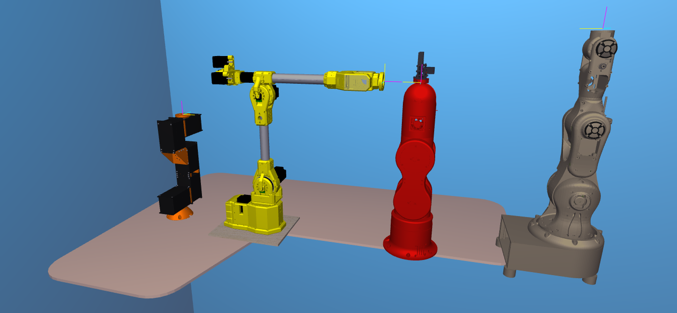
Some of the arms already available

Did you know Robot Overlord speaks natively to Marlin 3D printer firmware? Save even more time by using the same firmware.

You will need

  • A 3D CAD model of your robot arm
  • The D-H parameters of the arm in the same pose as it appears in your CAD file
  • The ability to write Java code for the Robot Overlord project
  • Some familiarity with git (forks, commits, pull requests)

Prepare your CAD file

It is easiest to export your arm into discrete moving sections, all of which with the same origin at the bottom center of the base of the arm (see slide 1). This is the same origin as the D-H parameters.

A meca500 robot, color coded with the base and six parts. the origin would be in the red part, on the same axis of rotation as the pink part

To help Robot Overlord run smoothly and to protect your IP it is recommended that you decimate the model by removing all hidden internal structures and components. Consider leaving screw heads while removing the threaded sections to save many megabytes of file size.

Each discrete section should be exported as an OBJ or STL file. (more on this later.)

The exported files should be located in /src/main/resources/[your robot folder]/. So if your robot is named Foo then it would be /src/main/resources/foo/. It would be consistent to name them base, j0, j1, etc.

Prepare your Robot Overlord class

In Robot Overlord’s /src/main/java/com/marginallyclever/robotOverlord/robots/robotArm/implementations you will find the collection of currently supported robot arms. It may be easiest to copy one of these classes and modify it for your purposes. Here is the minimum needed to code your arm. Every instance of Foo should be replaced with your class name.

public class Foo extends RobotArmIK {
	private static final long serialVersionUID = 1L;

	public Foo() {
		super();
		setName("Foo v1");  // the name that appears to users.
	}
	
	@Override
	protected void loadModel() {
		setBaseShape(new Shape("Base","/Foo/j0.obj"));

		// The DH parameters and the model file, added in order from J0 ... J5.  
		// angles are degrees, distances are centimeters.
		// name d r alpha theta thetaMax thetaMin modelFile
		addBone(new RobotArmBone("X", 7.974,     0,270,  0,170,-170,"/Foo/j1.obj"));
		addBone(new RobotArmBone("Y", 9.131,17.889,  0,270,370, 170,"/Foo/j2.obj"));
		addBone(new RobotArmBone("Z",     0,12.435,  0,  0,150,-150,"/Foo/j3.obj"));
		addBone(new RobotArmBone("U",     0,     0,270,270,440, 100,"/Foo/j4-6.obj"));
		addBone(new RobotArmBone("V",15.616,     0, 90, 90,270,-90,"/Foo/j5-6.obj"));
		addBone(new RobotArmBone("W",  5.12,     0,  0, 180,360,   0,"/Foo/j6-6.obj"));

		adjustModelOriginsToDHLinks();
		setTextureFilename("/Foo/texture.png");
	}
}

Now that the arm can be loaded by the app it needs to be on the menu of things that can be created by the user. In /src/main/java/com/marginallyclever/robotOverlord/EntityFactory.java add your new class:

public class EntityFactory {
	private static Class<?> [] available = {
		// ...
		com.marginallyclever.robotOverlord.robots.robotArm.implementations.Mantis.class,
		com.marginallyclever.robotOverlord.robots.robotArm.implementations.Sixi2.class,
		com.marginallyclever.robotOverlord.robots.robotArm.implementations.Sixi3_5axis.class,
		com.marginallyclever.robotOverlord.robots.robotArm.implementations.Sixi3_6axis.class,
		com.marginallyclever.robotOverlord.robots.robotArm.implementations.Thor.class,
		com.marginallyclever.robotOverlord.robots.robotArm.implementations.Foo.class,  // "Foo" must be your class name.
	};
	// ...
}

Now when you run the application and open the Add menu your robot name will appear.

‘Foo v1’ will appear on this list

Model size and orientation fixes

It is possible that your model appears in Robot Overlord too large, too small, or the parts are rotated in a strange way. My solution is to use a modelling program like Blender to rotate, scale, decimate, and even texture the model.

Forward and Up will control the rotation. +Z is always up in a Robot Overlord scene.

Selection Only will simplify your exporting from Blender. In the image above it will only export J2.

Scale will control the size. For models that appear in meters instead of centimeters, choose 0.1. If your model is imperial, you’ll probably want 2.54.

Now share it with …the world!

You’ve changed the code, you’ve massaged the model, it runs on your machine. Now to share it with everyone else! A pull request from you to the Robot Overlord project will tell the dev team that your stuff is ready. This is the best way to make sure your model gets in the way you want it.

No time? Let us do it for you.

We can add your model(s) to our system. Contact us! We’re looking to collaborate and work with everyone. Writing the class is free; preparing the CAD files is specialized work we outsource and will quote.

What about URDF files?

URDF is the Unified Robot Description Format, part of ROS, the Robot Operating System. ROS is a nice system but much harder to get running – part of the reason I work on Robot Overlord. Join the Robot Overlord github project and help make it happen? Imagine what we could do together!