Tutorials

Send Instagram Videos to Youtube with Raspberry Pi and Bash

Making Instagram videos is quick and easy.  Making Youtube videos is a laborious editing process that sucks the sunlight out of my soul.  People kept asking me if I have a Youtube channel and I was embarrassed to admit that yes, sort of, but no, not really.  I needed a way to send my Instagram videos to Youtube… a way to make the rock that kills the first bird bounce and kill the second bird!  With a bit of Bash scripting I was able to get my Raspberry Pi to automatically do this for me.  Read on for all the deets.

I used to use Zapier but they got dumb.  First they wanted to charge me to add extra steps to my one and only zap, then they said they couldn’t work ANYWAYS because Instagram tightened the data access rules.  I’m a big fan of IFTT but they can’t do it, either.  So!  Hand-rolled it is.

The pieces someone else made

I already had a Raspberry Pi 3 (?) set up to take timelapse pictures of my Prusa 3D prints.  I figure it’s idle most of the time, why not make it work a little harder?  Firstly I logged in and updated all the underlying framework.

sudo apt-get update
sudo apt-get upgrade
mkdir ig2yt
cd ig2yt

Then I installed https://github.com/rarcega/instagram-scraper to grab my instagram content.

sudo apt-get install python3
sudo apt-get install python3-venv
python3 -m venv env
/env/bin/python -m pip install instagram-scraper

and tested the instagram-scraper

/env/bin/instagram-scraper yourTargetChannel -u yourIGName -p yourIGPassword -t video

Next I installed https://github.com/tokland/youtube-upload by following the instructions in their readme.

wget https://github.com/tokland/youtube-upload/archive/master.zip
unzip master.zip
cd youtube-upload-master
sudo python setup.py install
cd ..
rm -rf youtube-upload-master

There were also a number of steps (in their readme) to install the .youtube-upload-credentials.json file to /home/pi/.  The file will contain your specific Youtube upload credentials and should remain secret.

That which binds them in darkness

Finally I was ready to test a bash script that would glue these other pieces together.  What you see here is the end result of an afternoon’s work.  It doesn’t show the testing steps along the way, most of which were later removed for brevity.  Test first!  Don’t blow up your following with a crazy upload machine.

#!/bin/bash

# the folder where mp4s will be stored
DESTINATION=imakerobots
PASSWORD=yourPasswordHere
MYACCOUNT=yourAccountNameHere
TARGETACCOUNT=nameItHere

# instagram-scraper looks in $DESTINATION to see what videos you've got
# and only grabs newer videos. youtube-upload uploads indiscriminately.
# we need the list of old videos so we don't upload old stuff again.
# get the list of files already in $DESTINATION
shopt -s nullglob
fileList=($DESTINATION/*.mp4)
#echo $fileList

# grab the 10 newest instagram videos
env/bin/instagram_scraper $TARGETACCOUNT -u $MYACCOUNT -p $PASSWORD -t video --maximum 10 --template {datetime} --latest

# upload each new video to youtube
for filename in $DESTINATION/*.mp4; do
if [[ ! "${fileList[@]}" =~ "${filename}" ]]; then
#echo $filename is new
filename2="${filename##*/}"
filename3="${filename2%.*}"
youtube-upload --title "$filename3" "$filename" --privacy="private"
fi;
done

# delete all but the 3 newest files so we don't fill the drive.
ls $DESTINATION -1tr | head -n -3 | xargs -d '\n' rm -f --

Final Thoughts

  • I didn’t setup youtube-upload in env because I’m a python newb.  I can barely ask “where it the toilet” in parseltongue.
  • I did setup this script to run as a cron job once an hour, every hour.
  • videos will be private so they don’t smash your subscriber’s data plan.  I had them originally set to unlisted but youtube still told everyone!  Many ugly emojis were received.
  • videos will be titled in youtube with the date and time of their original publication.
  • if you make the mistake of publishing a few of them and then pulling older instagrams and publishing those in a second wave your videos will be all out of sequence.  “Ha, ha,” says Youtube, “No fix for you!”
  • hese scripts don’t email me if the process worked, failed, or what have you.  They could be way more robust.
  • Special thanks to the helpful people in IRC freenode channel #bash and #python for helping with the many (many) different versions of python.

As always please let me know if I missed a step, if this was helpful to you, and so on.

3D Printing Projects

3D printable pipe connection adapter

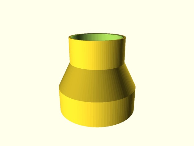
Recently a good friend asked me to make an adapter to connect the air hose from his vacuum to the air hose on his new scroll saw.  Both were, obviously different sizes.  3D printing to the rescue!

Shortly after he went home happy, I was thinking it would be great to have a tool that solves this problem forever.  Thingiverse has an option to make customizable, parametric designs.  So I whipped out SCAD modelling program and in about an hour crafted this tool that is free for everyone.

https://www.thingiverse.com/thing:3184173

You can change the diameter of the two hose ends, how far the hose ends sink into the adapter, and the thickness of the walls.  There is a small lip inside the shape to keep the hose from moving too far into the adapter.

In the first two weeks it has been remixed ten times already.  Fantastic!  If you find it useful, please tag me online or join my Patreon.

Robot Arm

Sixi Robot Arm update

I’m finally making progress on a new model.  Starting from the hand and testing as I go. 

I made a vault-like lock for a jewelry box and in it I used brass tubes as spacers and bushings.  It was so good I had to try and use bushings in my next design.  They’re suddenly everywhere!  Also all my parts that fit over a bushing have an extra large hole and a separately printed shaft collar.  That way the time to fix a part is low because only the collar needs reprinting.

It’s novemeber 12 today and I should (fingers crossed) have sensors reading the angles of the two axies by the end of the day.  Shortly after that I’ll be bending belts around a 90 degree angle (which I’ve never seen any DIYer do before in-person).

The tail end of this robot is going to need 4 gearboxes to get enough power so I’ve been bugging @Paul Gould about his excellent work, and I hope to print a few of his designs.  The lifting power of the elbow and the shoulder will probably be linear actuators.

Right!  That’s enough of that for now.

Makelangelo News

Makelangelo Software v7.17.0

Today I’m pleased to release Makelangelo Software v.7.17.0, the open source control program for our Makelangelo drawing robot.  This new version can now generate spirographs and read Scratch sketches.  Read on for all the details.

Minor improvements

First, some little details.  I’ve added a Help menu that contains the About tab and a link directly to the forums.

Makelangelo Spirographs

Generate Art > Spirograph will open the spirograph dialog and immediately generate the first spirograph.

By default the generator creates hypotrochoid drawings.  A hypotrochoid drawing is made by rolling a circle inside a ring, while keeping your pen at the same spot in the circle at all times.

Selecting epitrochoid will put the circle on the outside fo the ring.

The Major radius (R) value is the size of the ring.

The Minor radius (r) value is the size of the circle rolling around the ring.

The Scale (p) value is the distance from the center of the circle to the fixed point that the pen will follow.

The Sample (quality) increases the number of lines used to draw the shape.  More samples means smoother line.

Makelangelo Scratch Support

Scratch, from MIT, is the Minecraft of computer programming.  Each block does a different thing and blocks can only be combined in certain ways.

Supported scratch commands

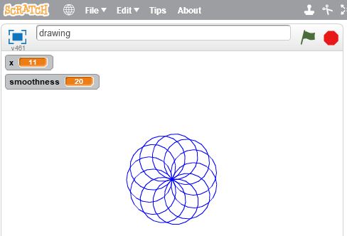
The scratch program above, when run (by clicking the green flag icon, generates a kind of spirograph.  (Total coincidence.)

Scratch programs can be downloaded from the website to your computer

And then uploaded to the Makelangelo software.  Remember to change the file type to SB2

File > Open > Type = SB2

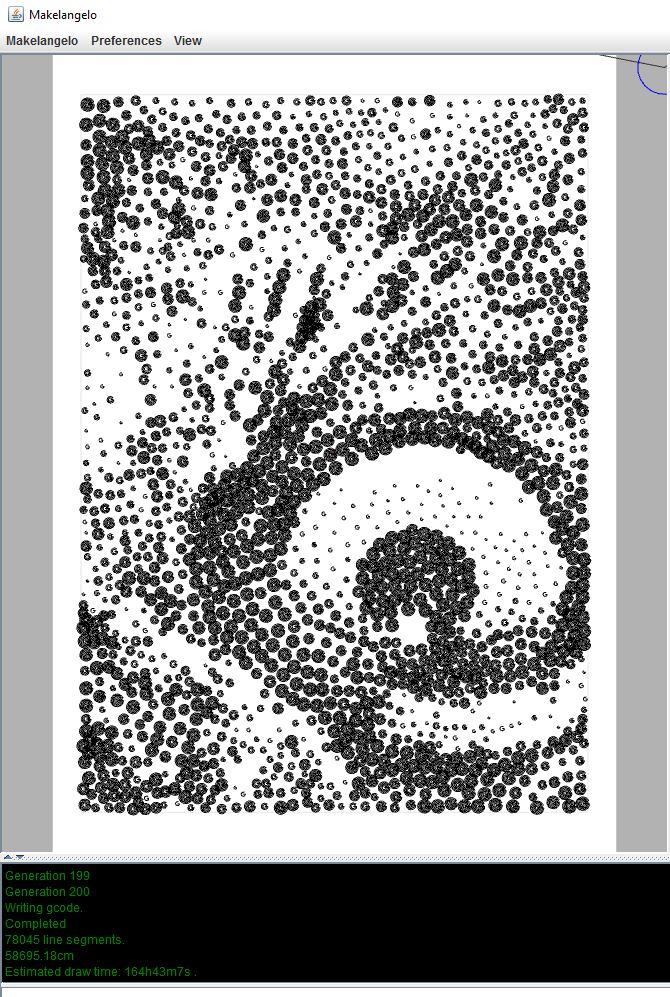
You should then immediately see the sketch drawn in the main view.

The extra lines are Makelangelos’s drawing of the pen holder

All scratch programs supported by Makelangelo Software v.7.17.0 must begin with a “When flag clicked” block.

Makelangelo Scratch (Scratchelangelo?) supports:

  • Move
  • Pen up/down
  • Turn and point in direction
  • Change x/y
  • Set x/y
  • Creating variables
  • Set variable to a number
  • Change variable by [operation]
  • Repeat [operation]
  • Hide, show, wait, and clear are ignored by Makelangelo and convenient for Scratch testing.
  • All other Scratch commands will probably cause an obscure error message.

There is no hard limit to the length of a sketch, the number of variables, or the complexity of a sketch.

As always, you can discuss these improvements in the forums.  We’d love to see what you make!

3D Printing Tutorials

Gcode Reference Guide

Here is a comprehensive list of all the gcode understood by the Makelangelo firmware.  Please use this guide to create your own gcode generator, to understand the gcode created by Makelangelo software, or to build machines that comply with the format.

Gcode commands should be common to most CNC machines and follow the same format as 3D printers, mills, lathes, and others.  For a more complete reference, please visit https://en.wikipedia.org/wiki/G-code.  Wherever possible we have tried to match the format.

Command structure

All commands are on separate lines (one command per line).  All lines end with a newline (\n). A return (\r) is not required.  Blank lines are ignored.
Any text after a ; is ignored. This gives you room to add comments inside a list of gcode commands.  Commands can be preceeded by a line number:

N[n] command;[checksum]

where [n] is some number >= 0 and checksum is a non-printable character (the XOR sum of all previous characters in the command, not including line number and semi-colon ‘;’ ).  Every correctly parsed command with a line number will increment the expected line number.

M Commands

M6 T[n]
Change to tool number [n].

M17
Engage (turn on) all motors. They will actively resist being moved and will obey commands.

M18
Disengage (turn off) all motors. They will not resist being moved and will ignore commands.

M20
List files on SD card (if any) to the serial connection.

M42 P[n1] S[n2]
Change digital pin number [n1] to state [n2] (0 for low voltage, 1 for high voltage)

M100
Print help message to the serial connection.

M101 A[n1] T[n2] B[n3]
Change software limits for axis [n1] to max/top [n2] and minimum/bottom [n3].  These limits are in millimeters.

M102
Print machine axis limits to the serial connection.

M110 N[n]
Change the next expected line number to number [n]. This means that the N[n] can appear twice on a single line with different values. The firmware should treat the first N as the current line number and the second N as the desired line number.

M114
Report the current state of the machine to the serial connection. This includes where it believes it is positioned, the feed rate, the acceleration, and possibly other values.

M117 [string]
Display messsage [string] on the LCD panel.

M226 P[n1] S[n2]
Wait for digital pin number [n1] to be in state [n2] (0 for off, 1 for on).
If P is not included, the default is the LCD button pin.
If S is not included, the default is off (0).

M300 P[n1] S[n2]
Play frequency [n2] for [n1] milliseconds through the LCD speaker.
If P is not included, the default is 250 (1/4s).
If S is not included, the default is 60 (a C note).
Some buzzers cannot play different frequencies.

G commands

G0 X[n1] Y[n2] Z[n3] U[n4] V[n5] W[n6] A[n7] F[n8]
G1 X[n1] Y[n2] Z[n3] U[n4] V[n5] W[n6] A[n7] F[n8]
Move the machine in a straight line to (X,Y,Z,U,V,W) at feedrate F and acceleration A.  All values are millimetres, except F and A which are in motor steps per second.  If any of these parameters are not included, the current value is used.

G2 X[n1] Y[n2] I[n3] J[n4] A[n5] F[n6]
G3 X[n1] Y[n2] I[n3] J[n4] A[n5] F[n6]
Move the machine in an an arc around a circle in the XY plane. The arc begins at the current position. The arc ends at (n1,n2).  The center of the circle of the arc is (n3,n4).  G2 is for clockwise arcs.  G3 is for counter-clockwise arcs.  If any of these values are not included, the value is unchanged.  I and J default to X and Y, respectively.

G4 P[n1] S[n2]
Dwell (wait) for n1 seconds and n2 milliseconds.

G28
Find home. This is different for each machine design. In general this means that the machine moves until it activates sensors to confirm its position. Many machines will refuse other G commands until G28 is completed. G28 is not run automatically when the robot turns for human safety.

G54 X[n1] Y[n2] Z[n3] U[n4] V[n5] W[n6]
Adjust tool offset for tool 0. This way the position the machine will report is the same as the position at the tip of the tool.

G55-G59
Adjust tool offset for tools 1-5. See G54 for more information.

G90
Absolute movement mode. All movement position values are relative to the machine’s frame of reference.

G91
Relative movement mode. All movement position values are relative to the current position.

G92 X[n1] Y[n2] Z[n3] U[n4] V[n5] W[n6]
Adjust the machine’s internal position value.

Non-standard Gcode Commands

The following commands are unique to Makelangelo firmware.  They will not appear in other machines.

UID [n]
Set the robot’s unique id number to [n].

D0 L[n1] R[n2] U[n3] V[n4] W[n5] T[n6]
Jog motors. Each letter represents a different motor. each [n] is a number of steps to move. the number of steps can be negative for a reverse jog. Not all machines have one motor per axis.

D4 [string]
Begin processing the file on the SD card called [string].

D5
Report firmware version number.

D6 X[n1] Y[n2] Z[n3] U[n4] V[n5] W[n6]
Set home position for each axis. When G28 completes the machine will teleport (G92) to this position.

D7 [Lnnn] [Rnnn]
Adjust Makelangelo calibration values for the length of left and right belts. Default is 1011mm.

D8
Report Makelangelo calibration values for left and right belts

D9
Save Makelangelo calibration values for left and right belts.

D10
Print hardware version number to the serial connection.

D11
Set up all default values for the Makelangelo 5.

D12
Assume the robot is as machine reference (absolute) position 0 on each axis. Move towards home switches and measure the distance. Then adjust D6 based on the measured distance.

D13
Adjust the pen angle on the Makelangelo. This is the same as a jog command. it is always absolute position in degrees.

D14
Report the machine style (kinematic model) to the serial connection.