News

Multi-material 3D printed Soft Robots

This video shows Multi-material 3D printed Soft Robots, which is a lot of fun stuff in one package. Researchers from the Wyss Institute at Harvard University developed a really fast way to switch materials while 3D printing and then used it to print robots that were a combination of soft and rigid parts.

Fantastic! I would love to see this used for easily dissolved support material, or circuits embedded into the bones of my robots.

circular weaving algorithm
Projects

The Challenge of Color Circular Weaving

What is circular weaving? Well to demonstrate here is a sweet weaving machine built by Barton Dring:

Some time ago I was asked by Marcus J if I knew how to get a computer to find the best way to place the threads. Having done a lot of algorithmic art for the Makelangelo Software, I was ready and willing to take on the challenge. My first version included weaving on circles and squares with black thread on a white background. It has since been forked by others.

Since then I have been struggling with the challenge of multi-color weaving. One example is seen in the fork link above. Another is instagram artist art.nitka:

I’m pretty sure that if I can get two colors to work then it should extend easily to many colors. Like… the jump is from one to all the things. Bit of a curve.

In the original method I start at nail 0. then i look at all the possible threads that could go out from there and find the one that most closely matches my thread color (black). Longer thread s can get a higher score, so they can easily get more points, but shorter thread s can have less error so it quickly averages out. Once I find the best thread to some other nail N, I place it and move to nail N. Placing it means that I draw the thread on a blank canvas AND I substract that color from the original image. This way I am unlikely to go back over the same pair of nails and eventually the image should be mostly erased, leading to a natural stop.

My first attempt at multicolor was to have a black thread and a white thread alternating back and forth over the image. It wasn’t great.

My second attempt I made two copies of the source image, one for each thread color. I built a list of threads for each image separately. On their own each one was sort of OK. I could put white threads on a black background or black threads on a white background and it was as good as the original method. But put them together and there were obvious problems – The threads didn’t mix in the right order.

Suppose the picture was a white circle in the middle of a black circle. The white threads should go on first to make the center, and then the black threads should cover the white ones around the edge. The problem gets more complicated with a human face, where a dark thread for the eyes might have light thread in the middle for the nose and around the edges for the sides of the face… and then dark again on the edges for the hair!

When the lines are to be combined in the finished image, I start with an empty stack B. I want to add line A to stack B so that when I look down through the stack the image is most-correct. Some white might be on top of some black and vice versa. Remember: it might not be strictly white-black-white-black-etc.
Lines are not woven together – a new white thread cannot be under previous white threads.

It is a convenient property that two lines only cross at a single point. I can find the intersection of two line segments to tell if the threads overlap at all and where, then look at the image at that point and ask “which of these two threads would be best on top?” It is very quick to calculate… but wrong.

Sometimes the answer is indeterminate: lines might be parallel, non-intersecting, or equally good.

Sometimes it would be better to put A under some B lines, because the total error is lower than A being above all B. eg, some error might make a better final image. How much? Where? I don’t know. Aye, that’s the rub.

What it means is that a simple binary sort won’t work. I tried BubbleSort and I tried a TreeSort. Neither of them works quite right. The end result has sorting that is obviously wrong.

The Color Circular Weaving Solution

I don’t know! I have to get back to work, so it will just have to simmer in the crock pot that is my skull. Until a solution is found… wish me luck and share this with your friends. Maybe you or someone you know has a hint.

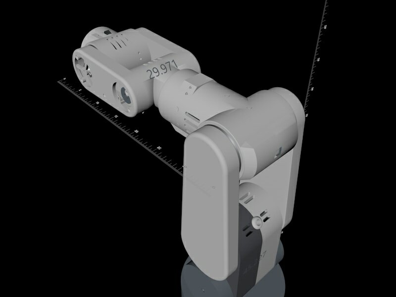
AR3 robot
Featured Artists

Feature: Chris Annin

Chris Annin is the creator of the AR2 and AR3 robots, which are available as open source plans and part sets that can be built in either aluminum or 3D printed plastic. At the time of writing this the AR3 costs about $1930.73 CAD + printed parts (or aluminum CNC parts) + assembly.

Where are you from – what’s your background?

I’m originally from the Portland Oregon area where I worked for Precision Castparts for 26 years in developing automation systems surrounding the investment casting process, these systems largely were centered around 6 axis robots for processes such as investment dipping, robotic water blasting and robotic grinding.  I’m currently located in Meridian Idaho where I work as a robotics systems engineer for House of Design where we design custom automation for a variety of industries. 

Do you have any specific plans to use the robot?

My initial goal in the project was to create the lowest cost robot possible using as many off the shelf components as I could. I wanted to teach myself robot kinematics as well as creating my own controls software.  I didn’t have a specific process in mind for the robot as much as the fact that I am just fascinated with robotics and wanted to build my own robot.  When I first developed the design I was working with the owner of Proturn Machining in Oregon City to create the prototype out of aluminum and the owners of Proturn are using the robot for some tasks in the machine shop including machine tending and applying a proprietary coating to customer machined parts.

There were a number of challenges in designing a 6 robot of this size that was low cost and practical.  Designing the mechanics especially around the robots wrist articulation was challenging.  I came up with a capstan type drive that utilized a lead screw through the entire upper arm of the robot that drives a carrier and pulley that I felt was a novel approach to solving the need for 90 degree power transmission along with low cost gear reduction. 

Capstan drive: the screw through the center is connected to rotate the wrist.

What did you learn while making this machine?

Learning the kinematics was a challenge as every book and paper on robot kinematics are written from the perspective of someone that already understands the process and uses mathematical jargon the rest of find perplexing. Editor’s note: too true.  Poorly written documentation is a pet peeve of mine so it was satisfying to create videos and kinematics models to help others to learn what I have learned so far. 

pixelated because I don’t have that person’s permission.

What is the part of this robot that is most satisfying to you?  Which part is the least satisfying?

Its been a lot of fun to see other people building the robot and participating in the project. It’s especially satisfying to have teachers and professors sending me pictures of their students building this robot in various classes and education programs.  Its been a fun project and I plan to continue developing the software and adding features, a couple on my list are interpretation of G-Code as well as integrated vision.  I am also looking into new creative designs for low cost mechanical solutions for a larger robot arm.

The AR3 software interface

Do you have a homepage?

The only homepage I have is my website and the blog on my website at www.anninrobotics.com.  I also have my LinkedIn profile.

Final thoughts

Looks like this project has a lot of room to grow and support to make it happen. I look forward to seeing it grow!

Also check out Chris Annin’s Youtube channel!

Makelangelo News

Bearing Tensioner Remixed!

The tensioner is a new idea to reach higher speeds by making sure the belts can never skip off the pulleys. It uses a rollerskate bearing – you’ve seen them in fidget spinners – and is 3D printed. Jason Garber remixed and improved the design, which delights me to no end.

Dr Evil Wait GIF - Find & Share on GIPHY

He said the middle pieces (2mm bend) is the his favorite. Here it is in action on Jason’s machine: